


SOME GAS-PRODUCER IMPROVEMENTS.
Page 32
If you've noticed an error in this article please click here to report it so we can fix it.
A Résumé of Recently Published Patents.
Some modifications to Col. D. J. Smith's portable gas-producer are described in specification No. 170,336, which is registered in the name of J. H. Paterson and others. The principal objects which it is hoped to attain by the improvements which are covered by the patent are: to reduce, if not to obviate altogether, any variations in the quantity of gas drawn from the producer, to supply the gas to the engine which is consuming it. under a pressure slightly above that of, the atmosphere, so as to ensure that a full charge of combustible mixture shall enter the cylinders; to provide means, other than a handcontrolled valve, whereby the mixture is maintained at constant quality; to improve the means of cleaning the gas, particularly of small solid particles and of water which may have been carried over with it from the producer, and to maintain the temperature of the fire. during such time as the engine is idling.
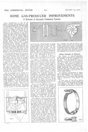
• The principal feature of the invention is a centrifugal fan, which is disposed at some point between the producer and the engine, the fan being so arranged that it draws the gas from the producer and delivers it to the engine. This fan is provided with a miniature sump, located at a point in its circumference opposite to the delivery pipe from the Ian. Suitable vanes, together with the effect of centrifugal force, divert any solid or liquid particles, which may be in the gas, into the sump. The latter is fitted with a revolving bucket which discharges the matter collected.
The arrangement of the details of a producer gasoutfit, snob as the one we are discussing, may be generally as depicted in the diagrammatic sketch which is reproduced herewith from the patent specification. On the extreme left is the producer. From it rune a pipe, along which the gas flows into the scrubber and cleaner, which is the second component. shown on the sketch —reading from left to right. From here the gas passes to the centrifugal fan,
and thence by a third length of piping which conducts the gas into the bell' mouthed pipe which is shown on the extreme right of the sketch. The gas there mingles with the quantity of air which is required to form a combustible mixture, which runs thence to the engine. On the pipe which leads from the fan to the bell-mouthed mixer is a branch pipe, in which is a valve; a similar valve is disposed in the pipe between this branch pipe and the mixer.
In ordinary circumstances, when the engine is running under load, the upper valve is closed and the lower one open, under which conditions the fan, which is engine-driven, delivers a full supply of
gas to the engine. When the load is shut off from the engine, the lower valve will be partly closed, either by hand or by means of a governor. The upper valve is then slightly opened, and the fan blows some of the gas out into the atmosphere, in sufficient quantity to maintain the temperature of the producer at such a height that, when a further demand for power comes from the engine, and the lower valve is opened accordingly, the upper one being at the same time automatically closed, the producer is able to respond at once.
Of -an entirely different character is the producer which is the subject of No. 170,523, by J. W. B. Stokes and another. The principal feature appears to be the revolving grate, while of interest only slightly secondary to this is the method of revolving the grate and the means for cleaning the ash-pan, notwithstanding the apparent interference which the driving gear would appear to offer to that operation.
The firegrate itself is mainly conical, that is to say, it, is circular in plan and conical in elevation. Its edge, however, is of wave form, so that at some parts the edge is higher than it is at others. This grate fits neatly into s. circular hole in the structure, and is arranged at such a height that its upper edge is in places on the same level as the hole in which it is placed, and at others is a slight distance below that level, the actual amount being adjustable. The idea behind all this is, that on account of its being conical, the grate will always be tending to move the burnt fuel towards the edge where, owing to the fact that part of that edge is below the level of the surrounding structure, the ash will be able to fall out into the ash-pan. Moreover, as the grate is being continu
ally revolved, the bed of fuel is, by reason of the wavelike form of the edge of the conical grate, given a continuous undulatory movement which, it is stated, assists the downward movement of the fuel, and prevents any tendency towards the formation of air pockets or clinker.
Other Patents of Interest.
The design of internal-expanding brake which is described in specification No. 170,407, by H. H. Hapgood, is of interest. The adjustment for wear of the shoes is made, not at the expander end, as is usual, but at the fulcrum of the brake. The method is a simple one and consists, in effect, of fitting an expander at the fulcrum, the said expander being adjustable from time to time, throwing the shoes further apart, but without interfering in any way with the actual brake setting.
An ingenious arrangement of vaporiz,er is described by the Austin Motor Co. in No: 170,439. The vaporizer, in duction pipe, and exhaust pipe together form a centinuous circle round the engine.
A neat type of cab for a heavy vehicle is the subject of No. 170,498, by S. E. Alley. It is designed for strength and simplicity, and also so that it will conveniently accommodate a windscreen.