


WHAT IS THE SIMPLF RM OF SIX-WHEELER?
Page 14
Page 15
Page 16
Page 17
If you've noticed an error in this article please click here to report it so we can fix it.
"The Commercial Motor" takes the Initi Advantages of an Increase upon :uring a Chassis Design in which all the Number of Wheels are Afforded,.
IN our last issue we set out in extenso, and with . amplification of detail, the advantages to be secured, in the case of goods vehicles and also of passenger-carrying vehicles, by the spreading of the load over more wheels than custom has hitherto ordained. We think that designers and users (because the man who pays the piper is, by common acceptance, the deciding factor in the choine of the tune that is being played) have been content to take four wheels for granted, and have failed to look beyond what is common practice for something better.
Railway coach designers long ago jumped from four to eight wheels, and after employing two bogie carriages per coach, have only just recently looked for something better, as evidenced by the new dining saloon train constructed by the Great Northern Railway. Here the. motive was a saving of weight for the purpose of reducing running costs and perinanent-way charges.
Motor designers can play a very important part in the recovery of the motor industry by advancing design to the points of higher efficiency, better results, greater safety and lower costs of manufacture. Of these the last is the least in importance, because lower running costs and maintenance charges play a bigger part than capital charges in all tables of working costs.
Following upon our article of last week, we approached a well-known designer, Mr. C. M. Linley, with a view to the production of a chassis design which should, in the simplest possible manner, satisfactorily incorporate tried and accepted devices by which the vehicle could be supported on six wheels (saving weight and cost by the user of reasonably small wheels and tyres), four ofl them driving, four of them steering and at least four of them braking.
Seeking Simplicity in Design.
We asked Mr. Linley to design his chassis primarily for association with a motor coach body, because the coach owner is the man with the greatest incentive to adapt that which is new and striking, and that which will offer distinct advantages to himself, to his passengers (from the point of view of comfort and convenience), and to local authorities, who may feel that they have a grievance because of the employment of heavy vehicles in large numbers on roads that were not originally designed to carry such weights at the speeds at which the motor coach is habitually • driven.
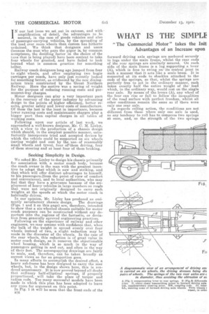
In our opinion, Mr. Linley has produced an eminently satisfactory chassis design. The drawings (Figs. 1 and 2 on this page) are, therefore, intended to show that a six-wheeled chassis suitable for motor coach purposes can be constructed without any departure into the regions of the fantastic, or deviation from generally aproved engineering practices. Following on the experience of railway and other engineers, we may assume with confidence that, when the bulk of the weight is spread evenly over four wheels instead of two, a slight reduction may be made in the diameter of the wheels. In the case of the rear wheels, this reduction is of great value in motor coach design, as it removes the objectionable wheel housing, which is so much in the way of passengers getting in and out, and often in the way of their feet. The accompanying drawings are fairly to scale, and, therefore, can be taken broadly as correct views so far as proportion goes.
In many efforts to accomplish the desired effect, a heavy sub-frame has been designed to carry the rear Wheels, but, in the design shown here, this is rendered unnecessary, it is now proved beyond all doubt that ordinary half-elliptical springs, if properly proportioned, • will take the place of torque and radius rods. Too many successful models have been made in which this plan has been adopted to leave any room for argument on this point.
In Fig. I it will he seen that the front ends of the 1316
forward driving axle springs are anchored securely to lugs under the main frame, whilst the rear ends of the rear springs are similarly secured. On each side of the main frame is a lug supporting a lever (A), which is free to swing onits central joint in such a manner that it acts like a scale beam. It is connected at its ends to shackles attached to the ends of the springs' so that, whilst the springs are perfectly free to act in the ordinary manner, each takes exactly half the entire weight of the load which, in the ordinary way, would rest on the single rear axle. By means of the levers (A), any wheel of the four can rise or fall to follow the inequalities of the road surface with perfect freedom, whilst all other conditions remain the same as if there were only one rear axle.
As regards rolling action, the conditions are not difierent from those where only one axle is used, as any tendency to roll has to compress two springs at once, and, as the strength of the two springs should be equal to the one usually employed, the resistance to rolling should be exactly the same as under usual conditions.
It is, of course, assumed that, as two axles and four wheels replace one single unit, the axles and wheels can approximately be made as if to carry only half the actual rear-axle load. This also applies tothe springs. It will be seen from the drawing that both rear axles transmit driving power to the road, and also that the forward driving axle is provided with universal joints and steering heads, so arranged that rotary motion can be transmitted to its wheels when at an angle. It will be understood that, in the case of such an axle, only a small amount of angularity is needed (approximately only half that of the front wheels), which does not present any difficulty in designing universal joints and their surroundings for the purpose.
By this arrangement all springs, shackles, etc., can he placed under the frame, and are consequently more out of the way than those which are outside the frame, and they can be covered by footboards, etc., which will have the effect of making the general appearance better, giving cleaner and more symmetrical lines.
There are so many thoroughly reliable arrangements for applying brakes to steering wheels now in existence that there should be no difficulty in choosing a design already tried and proved satisfactory for the brakes on the forward driving axle. As to the brakes on the rear driving axle, nothing but standard practice is called for. A balance of power by well-known means might be used to ensure the braking effect being evenly distributed between both driving axles. As to the employment of compound sprags, this seems to offer no difficulty; rather there is here a field for inventive genius.
Transmission of Power.
The engine is situated in the ordinary position, and the arrangement of clutch, gearbox, etc., can be as usual. A transmission brake can be used if desired, and is shown at the rear of the gearbox.
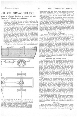
The forward driving axle is provided with a long boss centrally placed, as shown at E. This boss is merely a long bearing for a short shaft, which is connected by means of a cardan shaft to the drive through the gearbox. The short shaft which passes through E is provided at its front end with a lid in universal joint (D2), and at its rear end is connected to the spider of an ordinary differential gear, which is shown at B, without its casing, so as to make its action clearer. Mounted freely on this shaft is the bevel wheel (B1), which is formed integral with a gearwheel suitable for the silent chain shown at C. Mounted freely on the same shaft is the bevel wheel (135), which is formed integral with an ordinary universal joint (D).
Dividing the Driving Power.
It will be seen by this arrangement that the shaft which passes through E transmits the whole of the power to the spider of the differential (B), which evenly distributes it, one-half through B1 to the chain, and one-half through 132 to the universal joint (D), and then through the cardan shaft to the sliding universal joint (DI), and through that to the worm on the rear driving axle at F1. The half of the power which is transmitted through the bevel (B1) and the chain wheels (0) drives ths, worm of the forward driving axle (F), which is in every way the same as the worm (FI), excepting that it is slightly to one side to allow the main central shaft to pass it so as to preserve a symmetrical design of chassis.
The object of the differential (B) is to ensure the even distribution of power, and at the same time to allow for any slight difference in diameters of wheels and speeds, owing to the ftct, thatt in turning corners, the front driving axle -describes a larger circle than the rear driving axle ; consequently, the revolutional speed of the wheels is not the same, and, were it not for such a differential as B, grinding of the tyres would occur whenever a straight course was departed from. The differential (B) must not be confounded with the differentials contained in the worm boxes at F and FL, which are for the distribution of power between the wheels of their own axles in the ordinary way. It will be-understood that in running in a straight course the differential (B) runs round as a solid mass, its parts only functioning when the straight course is departed from. So far as this part goes, there is nothing that is not well known and tried practice.
Steering.
With the object in view of using smaller pneumatic tyres and distributing the load over a greater number of wheels, a simple meand is suggested in the steering arrangement. As larger front wheels
do not in any way interfere with body design, there is no need to reduce the diameter of them. Twin wheels are shown in Fig. 2 so as to distribute the load and enable smaller -tyres to be used. In the ordinary way there is an objection to this arrangement, as it makes the steering hard and causes tyre grinding. It will be noticed in Fig. 2 that not only twin tyres but twin wheels are shown. The steering head is shown partly inside the nearest wheel so as to make steering easier, sand the outer wheel is free to revolve relatively with its companion wl2eol.,. By the adoption et this plan stiff steering and tyre grinding is obviated2 while greater ground contact is obtained by very simple means. The front wheels would be connected by the ordinary Ackerman arrangement (not shown), but the steering heads are provided with arms (C) which actuate the rods (ID, which, in turn, actuate the levers or links (I) which are fulcrumed to the frame, as shown. Rods (K) connect from a point on J to the levers (L), which control the steering wheelsof the front driving axle. By this means a reduced motion is imparted to the steering wheels of. the central axle, and at the same time avoids all bends in the rods (H and K). These rods having to transmit motion by pushing and pulling, it is most important that there should be no bends in them. The rods (H and K) should be of ordinary construction, with a ball joint at one end to allow of rolling action of the frame.
As the amount of angle necessary for steering is only slight in the case of the wheels of the forward driving axle, there is no need to make any provision in the main channels for the wheels to clear.
The interruption of the rods controlling the steertug of the central axle by the links (J) is beneficial, as, besides reducing the motion, which is essential, J affords a support which prevents rattle and vibration, which would otherwise take place in such a very long rod if unsupported. The opinion of motor vehicle designers upon the drawings here submitted is most cordially invited, and alternative suggestions would be welcomed. Interest is being aroused in this subject among manufacturers and users and those who are responsible for road maintenance, and it must be remembered that a substantial advance in design, such as is hero foreshadowed, must of necessity he good for business.
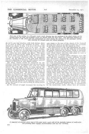
We also illustrate a couple of types of commercial vehicles which go to show that there is wonderful scope in this idea. The motor coach shown, for example, is full of good points. It is less like the goods vehicle than many that have for long been -on the market, and it is more like an enlarged private vehicle. Let it not be forgotten that there is no one more anxious to be regarded as a private motorist than the traveller by motor coach and even the charh-bancs tripper. Who is more anxious to be seen in, a smart, carriage-like char-k-bancs than the collier of Durham and Northumberland, or the cotton weaver of Lancashire, and his wife or sweetheart? In the better-class trade, where love of scenery, knowledge of history and architecture of the country are the paramount incentives to travel by motor coach, the c rdinary char-abanes is really not liked, and we say without hesitation that the trade iI1 inevitably flow in the direction of the up-to-date vehicle. The coach shown is mounted on a six-wheeled chassis, in which all the conditions have been complied with The wheels are small (in the illustration their very smallness makes the vehicle apparently very high—this is purely an optical delusion, however), the two rear axles transmit the driving power, and steering is effected by the two forward pairs of wheels. Wheel arches are avoided by the use of small wheels, and the carrying of the supporting rear wheels so far back means less overhang to the body and a more satisfactory solution or the luggage problem. The plan view shows that the: driver is virtually isolated from the passengers, a feature which, it will he found, will be developed in the near future, because it enables him to concentrate upon his work.
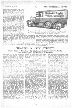
The van shown is intended for 25 cwt loads in a body that weighs about 10 cwt. It is mounted upon six pneumatic-tyred wheels, and is an ideal vehicle for the carriage of delicate and fragile loads. For such a vehicle the chemist, the tobacconist and cigar merchant, the china and glass dealer, the maker of cakes and pastries, and other people handling goods that are vulnerable to the effects of vibration, would welcome such a vehicle with open arms. Who will be the first among British manufacturers to place such a, vehicle upon the market?