


A Disc Brake for Heavy Vehicles
Page 64
If you've noticed an error in this article please click here to report it so we can fix it.
K'ROM J. Bird& and Dunlop Rubber Co., Ltd., 1 Albany Street, London, .N.W.1, comes, in patent No. 711,086, a
design for a disc brake intended for the heavier types of vehicle such as lorries and tracklayers. The scheme utilizes
a pair of rotary discs gripped between two sets of diametrically -opposed friction pads.
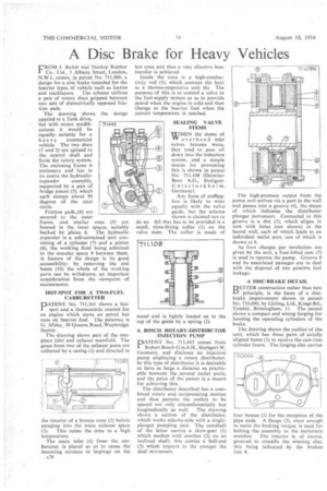
The drawing shows the design applied to a Tank drive, but with minor modifications it would be equally.suitable for a heavy commercial vehicle. The two discs (1 and 2) are splined to the central shaft and form the rotary system. The enclosing frame is stationary and has in its centre the hydraulic expander assembly, supported by a pair of bridge pieces (3), which each occupy about 90 degrees of the total circle.
Friction pads .(4) are secured to the outer frame, and similar. ones (5) are housed in the inner spaces, suitably backed by plates 6. The hydraulic expander is a self-contained unit consisting of a cylinder (7) and a piston (8), the working fluid being admitted to the annular space 9 between them. A feature of the design is its good .accessibility; by removing the end beam (10) the whole of the working parts can be withdrawn, an important consideration from the viewpoint of maintenance.
HOT-SPOT FOR A TWO-FUEL CARBURETTER
PATENT No, 711,161 shows a hotspot and a thermostatic control for an engine which starts on petrol but runs on heavier fuel.. The patentee is G. Allday, 30 Queens Road, Weybridge, Surrey.
The drawing shows part of the onepiece inlet and exhaust manifold, The gases from two of the exhaust ports are collected by a casing (1) and directed to
the interior of a bronze cone (2) before escaping into the main exhaust space (3). This raises the cone to a high temperature.
The main inlet (4) from the carburetter is placed so as to cause the incoming mixture to impinge on the A3R hot cone and thus a v6ry effective heat transfer is achieved.
Inside the cone is a high-conductivity rod (5), which conveys the heat to a thermo-responsive unit (6). The purpose of this is to control a valve in the fuel-supply system so as to provide petrol when the engine is cold and then change to the heavier fuel when the correct temperature is reached, SEALING VALVE STEMS
WHEN the stems of YV overhead inlet valves become worn, they tend to pass oil down into the induction system, and a simple means for preventing this is shown in patent No. 711,108 (DaimlerBenz A.G., StuttgartUnterturkheim, Germany).
Any form of stuffingbox is likely to wear equally with the valve guide, but the scheme shown is claimed not to do so. All that has to be provided is a small, close-fitting collar (1) on the valve stem, The collar is made of metal and is lightly loaded on to the top of the guide by a spring (2).
A BOSCH ROTARY-DISTRIBUTOR INJECTION PUMP
PATENT No. 711,443 comes from Robert Bosch G.m.b.H., Stuttgart-W, Germany, and discloses an injection pump employing a rotary distributor. In this type of distributor it is desirable to have as large a distance as practicable between the several outlet ports, and the point of the patent is a means for achieving this.
The distributor described has a combined rotary and reciprocating motion and thus permits the outlets to be spaced not only circumferentially but
longitudinally as well. The drawing shows a section of the distributor, which works side-by-side with a singleplunger pumping unit. The camshaft of the latter carries a skew-gear (1) which meshes with another (2) on an inclined shaft; this carries a ball-end (3) which imparts to the plunger the dual movement. The high-pressure output from the pump unit arrives via a port in the wall and passes into a groove (4), the shape of which indicates the distributor plunger movement. Connected to this groove is a slot (5), which aligns in turn with holes (not shown) in the barrel wall, each of which leads to an individual outlet port, one of which is shown at 6.
As four charges per revolution arc given by the unit, a four-lobed cam (7) is used to operate the pump. Groove 8 and its associated passages are to deal with the 'disposal of any possible fuel leakage.
A DISC-BRAKE DETAIL
BETTER construction rather than new principle, is the basis of a discbrake improvement shown in patent No. 710,690, by Girling, Ltd., Kings Rd., Tyseley, Birmingham, 11. The patent shows a compact and strong forging for housing the operating cylinders of the brake.
The, drawing shows the outline of the unit, which has three pairs of axially aligned bores (I) to receive the cast-iron cylinder liners. The forging also carries
four bosses (2) for the reception of the pipe ends. A flange (3), stout enough to resist the braking torque, is used for bolting the assembly to the stationary member. The interior is, of course, grooved to straddle the rotating disc, this being indicated by the broken line 4.