


Developments in Two-Speed Axle Design
Page 48
If you've noticed an error in this article please click here to report it so we can fix it.
DATENT No. 601,156 comes from
The Timken-Detroit Axle Company, Detroit, Michigan, U.S.A., and discloses the latest practice in the design of two-speed axles. The advantages lie chiefly in the easing of production problems; identical forgings can be used for the opposite halves of the differential cage.
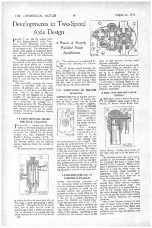
The vehicle propeller-shaft is universally jointed to the input shaft (I) which carries the bevel pinion (2). Actually, the pinion and crown-wheel are hypoids, the input shaft being higher than the crown-wheel axis, in the case of rearwheel drives. For driven front axles, the pinion is the lower; this feature is said to ease the load on the teeth in both cases.
The cross-shaft, carrying the crownwheel, is provided with two spur pinions of different size, which mesh with gears (3 and 4) on the differential cage. One or the other of the two pinions cart be engaged by a clutch member (5) and thustwo Speeds are made available. The slider is operated by a bell-crank (6). worked by a pneumatic actuator (7). The differential and the axle arrangements are of standard design and call for no special comment except the production feature already mentioned,
A LUBRICA.TING-OIL FILTER FOR BULK CLEANING
'nprovide a simple but effective iter for the bulk cleaning of lubricating oil, is the aim of a design shown in patent No. 600,820 by the British Tanker Co., Ltd., Britannic House, Finsbury Circus, London, E.C.2. A feature of the device is that the size of the filtering orifices can be adjusted during operation from the outside of the unit.
The drawing shows a typical example in which the dirty oil enters port (1) and flows into a space surrounding a helical spring (2). This spring forms the actual filter, and its effect can be varied by compressing it into a nearly closed position, or allowing it to expand until the space between the coil is of the desired A38 size. This adjustment is performed by a central stud carrying an external nut (3).
The oil, having passed between the coils, emerges in a cleaned condition from the outlet (4). To clean the unit, the inlet is closed, the spring opened wide, and compressed air is then blown through the outlet and escapes, Watt the dirt, from a special exit (5) from which the cap has been removed.
THE LUBRICATION OF BIG-END BEARINGS
IMPROVEMENTS in big-end Ittbrica1 tion are the basis of patent No. 601,310, which comes from the Austin Motor Co., Ltd., J. Rix and V. Appleby, all of Longbridge Works, Northfield, Birmingham. The invention is aimed at supplying oil+ to t h e peripheral point on the bearing where the need is greatest.
The drawing shows a part of a crankshaft in which I is the usual type of oilway running from the main journal to the crankpin. The novelty lies in the provision of a second duct (2) which branches from the mainsupply at the angle shown. The theory is that the extra duct feeds the trailing side of the cr.ankpin, a region which is heaviest loaded near the bottom of the stroke. This is due to the fact that at this point the piston still has considerable combustion pressure on it, and is also being vigorously retarded by the crankpin. To assist the action, a restricting plug (3) is located in the large duct.
A FISSURED SURFACE ON CHROMIUM PLATING
THE wear-resisting properties of chromium render it eminently suitable for finishing cylinder bores, but it is usually necessary to break up the polished surface into numerous fine grooves in order to retain lubricant. To achieve this by electro-chemical means is the aim of a scheme described in patent No. 600,818, by United Chromium Incorporated, New York, U.S.A.
This concern proposes to immerse the cylinder, after plating, in an acid bath, and, using it as a cathode, to remove some of the plating. According to the specification, the removal occurs in the form of fine fissures, leaving small plateaux untouched.
Numerous kinds of acid can be used, hydrochloric being an example, and a current density of from I to 3 amps. per sq. in. is employed. Current is applied for a few minutes, and by suitable control the fissures can be formed in the shape of slight pits or as " mud-cracks " reaching down to the base metal. The patent gives full details of both the plating and the etching solutions employed,
• A DISC-TYPE ROTARY VALVE ENGINE
A ROTARY valve is shown in patent No. 600,852, which comes from R. Peacey, 63, Mount Ararat Road, Rich mond, Surrey. Unlike most valves of this type, this one is in the form of a disc.
The drawing shows the valve incorporated in an air-cooled cylinder. It has a circular flat head (I) and a long spindle (2) for a journal. Much of the head is protected from the combustion flame by a plug (3), which closes the aperture through which assembly is performed. This unit has a partspherical. bore (4) at its inner end to form the combustion chamber.
The valve-head is cut into sectorshaped slots which uncover similarly shaped inlet and exhaust ports. The driving sprocket (5) is journalled on a stub on the cylinder head, and drives the valve through the medium of dogs, so as.to permit the valve to move freely in an endwise direction for sealing purposes.
One of the features claimed for this type of rotary valve is that the valveseat area is protected from flame heat on the power stroke. Lubrication problems are not easy of solution with rotary valves.