


A Self-governing njection Pump
Page 36
If you've noticed an error in this article please click here to report it so we can fix it.
A Résumé of Patent Specifications That Have Recently Been Published
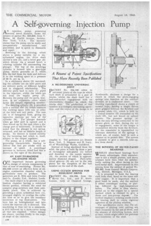
A N injection pump, possessing 1--several novel features, forms the subject -of patent No. 553,850, from V. Roosa, 16, Euclid Avenue, Ardsley, New York, U.S.A. The inventor claims that the pump can be easily and
inexpensively manufactured . and assembled, and if quick to dismantle and repair.
Referring to the drawing, which. shows a pump • suitable for a sixcylindered engine, the drive shaft carries a cam. (4); and a .bevel gear (5) which drives, via a second bevel, a rotating Cylinder (6) surrounding the plunger. The top of the eevolvipg cylinder is formed into a gear-type pump, shown 'generally at 7, which lifts the fuel from the tank and delivers it to the working space at a pressure of 50 lb. per sq. in.
In a stationary sleeve (2) surrounding the cylinder are six inlet ports and six delivery ports, at different heights and in staggered relationship. The delivery .ports lead to exits (1) piped
• to the injectors, whilst. the-inlets are fed, from the supply pump (7). Between the pump and the ports, however, is an adjustable valve which 191"MS the, output regulating member.
The rotating cylinder (6) is provided with a vertical slbt (3) which connects the working space with one or other of the inlet and exit ports. The cam (4) is of hexagonal form, giving six operative motions per turn of the cylinder (6). The plunger descends when p inlet port is opened and is then forced up by the cam when a discharge port is tincavered. It should be noted that the plunger is not sPringreturned, and 'has no definite length. of stroke. Its descent is caused entirely by the incoming fuel. which is, itself,
subject to 'the output regulator. • The pump, as a whole, has a selfgoverning characteristic, fending to deliver less fuel per stroke with an increase of speed. A centrifugal governor is, however, fitted and this is shown 'on the right of the drawing.
AN EASY-TO-MACHINE OIL-ENGINE HEAD (-NNE important feature governing 14..../the design of certain components is' that of ease of machining. Patent No. 554,028 covers an :effective form of oilengine combustion chamber which. is particularly easy to produce. The patentee's are E. Ellis and John Fowler. and Co. (Leeds), Ltd., Hunslet, Leeds. . The main object is to provide a combustion chamber 'having a restricted 'throat portion, without the need for complex plugmembers and their associated joints. This is achieved byproviding a plain cylindrical bore (1), arranged slightly to Overlap the cylinder bore so as to give the necessary
restriction at top dead-centre. The bore has an hemispherical end into whichthe injector (2) is directed. The machining is thus cut to a mininmim, a drill followed by a form-cutter being all that are required. Other designs are shown, varying chiefly in the angle of slope of the chamber, A RE-DESIGNED UNIVERSAL JOINT PATENT No. 554,106 refers to . universal joints. of the type in which each shaft is articulated to a pair of blocks, whilst the shaft itself has a ball-and-socket engagement with an intermediate member in. which the blocks slide. The production of this member is complex-Machining .operation. and the object of 'tiltdesign' is to
simplify it Th"e patentees are Dennis Bros., Ltd., J. Simpson and B, Lucy, allot Woodbridge Works, Guildford. • Instead of being niachined from the solid, the piece is built tip from a pair of. rectangular side-plates (I) bolted and dowelled to the centre member. (3), the section of which is approxi mately diamond shaped. Part-cylindrical grooves (2) are cut in the side plates for the reception of the ball member on the end of the shaft.
USING CLU-WH SPRINGS FOR RESILIENT DRIVE PATENT No. 554,238, from the Rover Co., Ltd., and P. Sc:ottIversen, both of Chesford Grange,
Kenilworth, discloses a design for a clutch in which the plate-engaging springs also lunction as the resilient
member Of: a:cushioned drive. The drawing reproduced shows a clutch of normal type, having a single driven plate gripped'between the flywheel and a 'presser -plate (1), which is held by a conical member (2) journalled on the shaft (3), but 'not keyed or spliued thereto. The pressure springs (4) form the only driving connection to the presser plate, so that, during the act of engagement, some of the torque is transmitted directly from the flywheel, but the remainder is transmitted by sideways distortion of the 'Springs 4, which .are, of course, held in such a manner as to permit this. The system is claimed, to give a smooth take-up, free from shock.
THE BONDING OF SILVER-FACED BEARINGS
WHILSWHILST silver-faced bearings have advantages, their -manufacture is 'not a simple process, and Many schemes haVe been tried for satisfactorily uniting the silver facing to the hard-metal-shell. Improvements in this process form the subject of patent No. 5:53,363, from General Motors Corporation, Detroit, Michigan, U.S.A.
• It is proposed to form the .bearing shell from steel, faced on the inner side with' copper. It is important that a good bond be' made, and the method is either centrifugal casting, . or Plating, followed' . by ' high-temperature fusion. The silver is then electroplated on to the copper by a special method which is claimed to give a dense and non-porous deposit. _The method employs a rotating anode inside. the bearing shell to create vigorous agitation of the plating solution.. The spedfrcation.:states that the advantages or plating, over casting,. are dual—economy in the use of silver, and the absence of disturbing factors, such as heat, which niight affect the provioui beat-treatment of the steel.