


Fitting New Piston Rings in Steam Engines.
Page 18
Page 19
If you've noticed an error in this article please click here to report it so we can fix it.
By an Engineer-in-Charge.
The necessity for exercising the _greatest care in the fitting ot new piston rings is often overlooked by drivers and mechanics, and new rings are frequently put in which are little better than the old ones, so far as keeping the piston steam tight is concerned. Taking into consideration the high pressures at which steam is employed at the present time, and the number of revolutions which the crankshaft of a steam wagon or tractor makes in the course of a day's work, a rough idea of the amount of coal wasted, and the consequent loss of power which results from badly-fitting piston rings can be formed. In many cases, the rings are not examined as often as they should be. They are allowed to become worn to such an extent as practically to be useless, tnthey are probably broken _through some cause or other. In cases where the boiler is at all addicted to priming, after taking up dirty water, gritty matter is carried into the cylinder, where it causes the ring to be cut and scored, more frequent examination of the cylinder and piston rings is absolutely necessary.
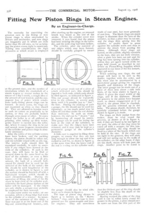
After the joints of the cylinder covers have been broken, and the packing drawn, the piston should be taken out, and the cylinder wiped with an oily rag. The interior walls should then be examined carefully, in order to ascertain if any ridges have formed at the ends of the cylinders. If such is the case, they will have to be filed or scraped down to the same level as the bore of the cylinder, or even a little
tower. If the ridges are at all pro, minent, the back of a smooth halfround file should first be used for the removal of the bulk of the metal : the file should_ be used lengthwise of the cylinder, as is Shown in figure t, and the surface should be finished off with a half-round scraper, whish should he iused circumferentially. Duringthe -operation of filing, the point of the file must be kept clear of the cylinder wall, otherwise the hard glossy surface of the latter will be damaged. If the ridges are only slight, a scraper may probably be employed for their removal.
A case came under my nofice, on one occasion, where a sharp ridge had worn in the cylinder of a tractor. In ignorance of the existence of this ridge, a liner was put in at the front end of the big-end connecting-rod brasses,. and, after starting up the engine, an unusual knock was heard at the end of the stroke. ‘Vhen the cylinder cover was removed, it was found that the piston had been striking the ridge in the cylinder, and the junk ring had been broken.
The cylinder, after the removal of any ridges which may have formed, should be carefully gauged by means
of a red gauge made out of a piece of 1-inch mild-steal rod ; this should be tapered at both ends, which ends should be filed square., as indicated in figure 2. This rod gauge should be repeatedly tried in the cylinder, in several positions, until it is possible just to " feel " the bore. During the making of such a gauge, the file should not be used ton vigorously, or too much metal may be taken off and thus make the rod shorter than necessary. In such an event, however, the rod can be " drawn " out by hammering all round its centre. This gauge can be used for trying the bore at the ends of the cylinders, to make sure that the ridges have been removed, and it may then be kept as a permanent gauge of the cylinder's diameter.
A little care is required in filing these gauges, to ensure that they are just long enough to allow the top end to be rocked to and fro, as shown in figure 3, at the same time that the lower end of the rod is resting en the cylinder wall ;
the gauge should also be tried sideways, as is shown in figure 2.
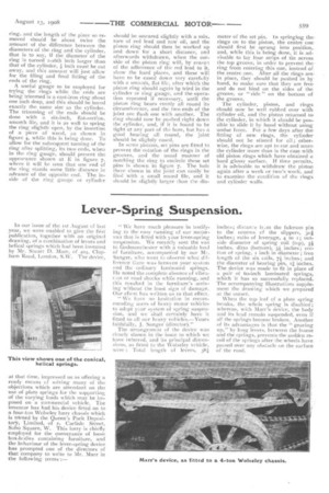
The type of piston ring shown in figure 4 is known as the " Ramsbottom " ring, and is the type in most general use for steam-wagon and tractor engines. They are sometimes made of cast steel, but more generally of cast iron. The blank rings are made larger in diameter than the bore of the cylinder, so that a piece may be cut out, and the rings then sprung into the cylinder, to enable them to press against the cylinder walls and thus to prevent the steam from passing the piston. Although these rings are turned, on the outside, slightly eccentric to the bore, they are not truly circular, after a piece has been cut out and the ring has been sprung into the cylinder, unless they are again turned (with the gaps held closed, as described in our article on Piston-Ring Supplies which appeared in our issue of the 6th instant, page 538 ante).
When ordering new rings, the rod gauge will have to be sent to the maker, together with the order, and this must also be accompanied by a sheet-metal gauge giving the required breadth and thickness of the rings. The latter gauge can be made out of a piece of sheet iron about 1-16th inch thick, of the form shown in figure 5, where A gives the exact width of the rings, and B the thickness. Should the grooves in the piston have become worn, as shown exaggerated at C in figure 6, the piston must be chucked, and the grooves trimmed up in the lathe. The piston should, therefore, be carefully examined before the gauge shown in figure 5 is made.
The rings, on their receipt from the maker, must be tried round the grooves, as shown at D in figure 6, and, if they are found to be too tight at any part, the sides of the ring must_be eased off with a scraper ; for this lastnamed operation, the ring should be fixed to a piece of flat board, which can be held in the vice. If the rings are too tight in the grooves, they will stick and will not spring out to the walls of the cylinder ; on the other hand, if they are too slack, steam will leak past the rings. Another point to be noted is
that the thickest part of the ring should be slightly less than the depth of the groove in the-piston. . Having scraped the sides of the ring until it can be rolled freely round the groove in the piston, a piece should nov be sawn out frcm the thin part of the
ring, and the length of the piece so removed should be about twice the amount of the difference between the diameters of the ring and the cylinder, that is to say, if the diameter of the ring is turned r-i6th inch larger than that of the cylinder, inch must be cut away, and this amount will just allow for the filing and final fitting of the ends of the ring,
A useful gauge to be employed for trying the rings while the ends are being trimmed is a cast-iron ring about one inch deep, and this should be bored exactly the same size as the cylinder. The trimming of the ends should be done with a six-inch, flat-section, smooth file, and it is as well to spring the ring slightly open, by the insertion of a piece of wood, as shown in figure 4, while this is being done. To allow for the subsequent turning of the ring after splitting, its two ends, when in the ring gauge, should present the appearance shown at E in figure 7, where it will be seen that one end of the ring stands some little distance in advance of the opposite end. The inside of the ring gauge or cylinder should be smeared slightly with a mix_ ture of red lead and raw oil, and the piston ring should then be worked up and down for a short distance, and afterwards withdrawn, when the outside of the piston ring will, by rew.0.:1 of the adherence of the red lead to it, show the hard places, and these will have to be eased down very carefully with a smooth, flat file, after which the piston ring should again bp tried in the cylinder or ring gauge, and the operation repeated if necessary, until the piston ring bears evenly all round its circumference, and the two ends of the joint are flush one with another, The ring should now he pushed right down the cylinder, and, if it is found to be tight at any part of the bore, but has a good bearing all round, the joint should he slightly eased.
in some pistons, set pins are fitted to prevent the rotation of the rings in the grooves, and the usual manner of notching the ring to encircle these set pins is shown in figure 7. The hole there shown in the joint can easily be filed with a small round file, and it should be slightly larger than the din meter of the set pin. In springing therings on to the piston, the centre oneshould first be sprung into position,. and, while this is being done, it is advisable to lay four strips of tin across the top groove, in order to prevent the
from entering this one, instead of. the centre one. After all the rings are. in place, they should be pushed in by hand, to make sure that they are freeand do not bind on the sides of the groove, or " ride " on the bottom of the groove.
The cylinder, piston, and rings should now be well rubbed over with cylinder oil, and the piston returned to< the cylinder, in which it should be possible to slide it by hand without using undue force. For a few days after the fitting of new rings, the cylinder should not be stinted for oil; other-wise, the rings are apt to cut and scorethe cylinder more than is the case with old piston rings which have obtained a hard glossy surface. If time permits, it is advisable to withdraw the piston again after a week or two's work, and to examine the condition of the rings and cylinder walls.