


Dynamo-cum-brake Exhauster
Page 76
If you've noticed an error in this article please click here to report it so we can fix it.
nIL-ENG1NED vehicles employing
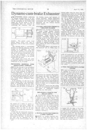
vacuum braking have to be provided with a special exhausting pump for the operation of the brakes, and patent No. 741,767 shows a way of economizing space and material by combining the exhauster with the dynamo. The patent come S from Simms Motor Units, Ltd., and G. Rackham, both of Oak Lane, London, N.2.
The drawing shows a conventional dynamo (I) with the exhauster unit (2) formed on its end-plate. No extra bearings are needed, there being only one at each end of the combined unit. Moreover, the same driving belt serves for the two purposes. A running sealing ring (3) is fitted to the spindle between the two units.
The patent also covers the same arrangement applied to driving an aircompressor or an oil pump.
PREVENTING SKIDDING WITH ARTICULATED VEHICLES
ONCE .the rear part of an articulated vehicle starts to skid, the driver may lose control of it, because there are no forces available to oppose its sideways movement. To provide such a correcting force is the aim of a scheme disclosed in patent No. 741,832 (D. Smith and Adrolic Engineering Co., Ltd., Clober Road, Milngavie, Dunbartonshire).
In the drawing, 1 is the rear of the tractor chassis and 2 the semi-trailer which is articulated about the kingpin (3). The invention Consists of a hydraulic ram (4) which is pivoted to the tractor at 5 whilst its piston 's pivoted at 6 to the trailer. When the trailer swivels, the ram will have to lengthen, and it is able to do this because its two ends are connected by a pipe (7).
If this pipe be obstructed, however, the trailer will be locked at whatever angle it may happen to be, and this is the essence of the idea. A valve (8) in the pipe can be operated by the pressure in the master-cylinder (9) of
B42 the braking system and operates in unison therewith. Partial application of the brakes gives partial resistance to articulation, but if the pedal be fully depressed, the two vehicles become locked together.
AN EASILY SERVICED TORSIONAL VIBRATION DAMPER
DATENT No. 741,744 (T. Hindmarch,
Lindo Lodge, Stanley Avenue, Chesham, Bucks), refers to torsional vibration dampers as fitted to engine crankshafts. These consist of two elements, frictionally united, %id+ a restoring spring to bias them into thw central position. The patent discloses a design in which the springs can be adjusted or replaced through a cover plate without the need for dismantling the whole unit.
The drawing shows a part-section of the proposed unit in which rings (1 and 2) form one element; this frictionally engages the other one which is a central ring (3). The relative movement between the two is limited by abutments consisting of coil springs (4). These are held between half-round endplates (5) which nest in recesses in the two sets of discs.
By applying a special tool, the spring units can be compressed and extracted for repair or adjustment without disturbing any other parts.
BREAKDOWN VEHICLE FOR ROUGH GOING
A RECOVERY vehicle that can be used on the roughest of ground
is shown in patent No. 741,213. The vehicle is in the form of a two-wheeled trailer and is equipped with a pivoted jib that can be extended rearwards to reach the front of the disabled vehicle.
Once lifted, the jib is then retracted to a position over the road-wheels, so that the vehicle is then quite stable. (Daimler Benz A.G., Stuttgart-Unterturkheirn, Germany.) A TILTING STAND FOR WORKING UNDER VEHICLES
WHILST the modern high-lift platvv form is much better than the pit for working under a vehicle, both devices suffer from the defect that the operatorlas to work over his head, an awkward and tiring position. A more convenient attitude is permitted by the use of a device shownin patent No. 741,783 (I. Ncuteboom, Nicuwstraat 8, Spijkenisse, Holland).
In this scheme, the vehicle is run on to a cradle that is trunnioned on crossbeams; the latter can then be raised and tilted as shown in the drawing. Ills gives the operator a much more comfortable working position.
The • crossbeams (1) carrying the trunnions can be raised or lowered in unison by cables wound on a powerdriven drum (2). This gives a direct level lift. If, however, one side of the
cradle be anchored by the attachment of a compression bar (3), this side is prevented from rising when'the cables are hauled, and the cradle is compelled to tilt as shown. If the vehicle be adequately secured, it is possible to turn it through a complete right-angle with safety.
A TOOL FOR EXPANDING OUTER COVERS
TO make an inspection or to repair damage to a tyre, it is usually necessary to gain free access to the interior, and to do this to modern tyres often demands great force. A tool of use in this respect is shown in patent No. 741,194, (D. Cifirk and Associated Component Manufacturers, Ltd., Battle Road, Hailsham, Sussex).
To use the device, the tyre is placed with its tread abutting plate I. The hooked arms (2) are then swung round
to engage with the edges of the bead. A pedal-operated hydraulic jack (3) then forces the tread upwards, causing. the arms to swing outwards and downwards about pivots 4. The beads are thus widely separated and the tread area is forced upwards into a convenient position for carrying out any repairs that may be found necessary.