


ALTERING AND REPAIRING OLD MODELS.
Page 29
If you've noticed an error in this article please click here to report it so we can fix it.
Jobs Carried Out by Our Driver and Mechanic Readers.
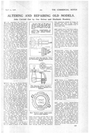
TN the experience of " W.J.," of 'Peckham, the bronze thrust washers employed in the rear-wheel bearings of lilandslay vehicles get scored in the course of time, and, owing to the. considerable weight of these wheels, it is not an easy matter to handle them or to find a lathe large enough to aecommodate them when it is proposed to skim Ill) the worn faces. In these circumstances a cutter bar, designed by
W.J.,',• may be useful to other users of these vehicles. The majority of the parts are used elsewhere on the Maud:day ; for example, the bar itself is the bottom half of a steering column. Taking this part, " W.J." made a
square hole in the shaft, 9 ins, from the shoulder at one end, and into this he slipped a tool 51 ins, long, which skims the worn faces.
It is necessary, of course, to keep the bar absolutely central in the hub when cutting ; therefore a spigot 7 ins, in diameter on the shoulder must be made and fitted, so that it can fit into the huh. At the other end another spigot must be turned and fitted to register
' in the opposite. end of the wheel hub, one of its faces having a recess in. deep to take a ball thrust race—one of the type used in the clutch withdrawal will do. The centre hole of this race will be too large, and it is therefore bushed with brass, and an adjusting nut is run down the thread on the end of the column which, naturally, pulls the spindle through the spigot and ball race, thus pulling the cutter harder up against the face upon which it is working. This, of course, provides the feed, and the actual turning motion is cruised by rotating a totnray bar which passes through a hole drilled in the spindle.
THOSE who use the B-type Daimler , chassis will be interested in the method adopted by " G.J.H.," of Letchworth, for fitting a dynamo. Belt drive is, of course, adopted, power being taken from the vibration damper On the front end of the crankshaft: The mounting of the pulley requires a certain amount of care and thought. It will be found that there are two brass plugs in the damper ; these should be drilled, tapped out # in. and studs fitted • in the holes, allowing sufficient length
. to separate the pulley from the damper by about j in. The best way to ensure this spacing is to use tubular distance pieces slipped over, the studs, and if they are threaded internally they will serve as lock-nuts. If less space than this he allowed the -dynamo belt will foitl the oil fillers in the damper.
The dynamo pulley is drilled to pass over these studs, care being taken, Of course, 40 drill the holes so that it will run true. TWO more attachment points for the pulley consist of setScrews and lock-nuts, so that it is fourpoint attached. By means of the studs the damper and pulley may be
trued up so as to run parallel.
The dynamo itself is carried on a . platform supported by two brackets, one of which is bolted to the chassis
frame side-member and the other to the cross-member which goes over the crankcase at the front end and supports the engine. The dynamo rides on a hard-wood cradle and is held in position by a strap with threaded ends, which pass through holes in the platform.
Belt adjustment should, of course, be provided, and when a 1-in. Whittle belt is employed the available range is about three links.
ON vehicles fitted with Tylor engines, clutch centre nuts are apt to work loose, and " W.H.S.," of Middlesbrough, describes his method of locking them in position on the clutch centre. With the nut, in position a fin, hole is drilled through it at right angles to the clutch centre, the hole passing through the stem and bush, the drilling being continued so that holes are made exactly opposite each other. A long fin, bolt is then slipped right through the parts and the nut is tightened down, preventing the centre nut slackening off.
EXTRA-AIR valves for Leyland vehicles can be easily made, according to " G.W.," Of Bolton, the parts being, in the main, scrap material. About 9 ft. 6 ins, of copper wire of it-in, diameter is required, also One gas tap and one gas union of the same bore, together with a piece of rubber tubing. The induction pipe is drilled and tapped to take the union, into which fits the nine, and the other end is surmounted by the gas tap dipped to the steering column just below the wheel. The pipe run is carried from the engine to the dashboard along the dash, where it is supported by two clips and through a hole in the board. In order to avoid trouble in case of dismantling, the rubber tube may be used as a joint in the pipe in order to enable it to be removed in two pieces.
THE blower of a Yorkshire steam wagon in the hands of " A.W.," of Dewsbury, once showed reluctance to work; he found that the trouble was due to the end of the blower pipe being too far above the fire to be effective. To overcome this trouble a special pipe was made, and instead of its extremity being above its horizontal portion the pipe was bent so as to bring the nozzle a suitable distance below it. This meant that the steam jet, instead of blowing into the funnel, discharged much lower down, approximately, in this case, on a level with the centre line of the steam dome.
ON some A-type Straker-Squire vehicles the universal-joint pins are neglected because the greaser is not easily reached. "G.J.," of Gloucester, suggests an alternative lubrication scheme. A hole should be drilled in the adjusting square of one of the bushes, tapped out 5-16 in. and fitted with a greaser about 1 in. in diameter. Grease is, of course, fed into the bush, and it travels through the hardened hollow star, supplying the other blind bushes in its course. " G.J." points out that care must be taken in adjusting these bushes to obtain perfect alignment, otherwise the propeller shaft will be thrown out of line, with expensive consequences.