


Abridgments of Interesting Patent Specifications.
Page 24
If you've noticed an error in this article please click here to report it so we can fix it.
No_ 1,754: dated January 28th, 1904.— II. de la Valette.—This invention relates to electric ignition devices for multiplecylinder explosion engines, and has for its object to provide for the use alternatively of a magneto machine or an accumulator for the production of the sparks, only one induction coil being utilised in connection with each of the sources of current whatever the number of cylinders. a Indicates a magneto machine and b a make-and-break device of known construction arranged in shunt with the magneto machine in a circuit (c, d, e), which includes a primary coil ; the ends (c and e) of the circuit are earthed: gr indicates an accumulator or other suitable battery mounted in series with a rotary switch or make-and-break device (4) in a circuit (1, j, e), which includes a second primary coil (k), a trembler (m), and a screw contact or terminal (a) of a wellknown type. These two circuits also include two switches (o and p) connected by a bar (q) in such a manner that one of the circuits is open whilst the other is closed. With the primary coils (f and le) are combined respectively the secondary coils (r and s), connected at one end to the common terminal (e), and at the other end to a circuit (t, u) through the medium of a switch (v), also coupled to the switches 1,c, and in by the bar (q) in such a manner that the circuit (e, t, a) is closed either through the coil (r) or the coil (s), according to the position of the bar (y). In the circuit (e, 1, u) there is also arranged a current distributor (2), having the rotating segment (w), and as many brushes (x) as the motor has cylinders, each of the said brushes being connected to one of the terminals of the sparkingplug of the corresponding cylinder (y), the other terminal of the plug being connected at u to the cylinder or to earth. The armature of the magneto (a), its make-and-break devise (b), the switch (1x), and the distributor (it) are actuated synchronously with the motor, for instance, through the medium of a common shaft not shown in the drawing. Furthermore, the segment (w) is made of such a width that during each of its movements in front of a brush (r1 the period of contact between the segment and the brush corn mences previously, and ceases subsequently, to the period during which the alternating and intermittent currents are generated corresponding to this movement, in order to avoid the formation of sparks on the distributor. When the bar (y) is in the position indicated in the drawing the accumulator circuit is broken at p, and the magneto circuit is closed; the magneto-electric device (a, b), or other equivalent device, is controlled in such a manner as to produce abrupt variations of current in the coil (1), and consequently induced currents In the coil (r) at the instant at which the central portion of the segment (w) passes in front of the different brushes (x), whereby sparks arc produced in the various cylinders (y) in succession. When the bar (q) is pushed to the left the magneto circuit is broken and that of the accumulator can be closed through the medians of the rotary switch (4) and of the trembler (m), abrupt variations of current being produced in the coil at the moment at which the central portion of the segment (w) passes in front of the brushes (x). To obviate the production of sparks, switches (i and 2) may he employed in connection with the circuits (e, (1, e and 1, j, 4), and disposed in such a manner as to place the magneto and the accumulator in short circuit when these circuits are closed.
No29)4og dated, October ist, 1904.— Louis Renault.—A constant level reservoir (1) supplies the petrol to two nozzles (2 and 3). The nozzle (3) opens into a chamber (4) which is in direct communication with the motor, while the nozzle (2; opens into a chamber (5) communicating with the mid chamber (6) of three superposed cylindrical chambers. The upper part of the mid chamber communicates with the chamber (41 through an opening (7). A cylindrical sleeve (Si can move up and down in the mid chamber (6) so as to cover, Or uncover, openings (9) connecting the said mid chamber (6) with the aforesaid chamber (5). The sleeve (8) is carried by a rod (to) guided by a screw )10 thereon engaging in a nut in the upper part of the carburetter, and is normally held in its lower position by a spring (12). The rod (to) is provided, in the lower chamber, with a disc (x,3), the diameter of which is nearly equal to that of the said chamber. The lower part of the lowermost ilaniher communicates with the atmosphere through openings (14), and, through openings (x5), with the chamber containing the spraying nozzle (3). The air is drawn throagh the openings
from is tub?. near either the exhaust pipe, or the radiator, or other hot place, so that the air which enters the carburetter is hot. 'rho operation of the carburetter is as fol lows :—On starting the motor when the vacuum is low, air enters the carburetter only through the openings (4), and passes through the annular space between the periphery of the disc (13) and the wall of the lowermost chamber. The air then passes through the opening (15), circulates round the nozzle (3), • and thence reaches the motor in a carburetted state through the chamber (a). When the speed of the motor increases the vacuum increases and acts on the disc {13), so that it is lifted and, at the same time, the said disc is slightly rotated owing to the screw ft) working in its nut. The disc (13), on being raised, shifts the sleeve (8) which, more or less, uncovers the openings (9). A fresh quantity of air, which has entered the carburetter through the openings (16), and has become carburetted by circulating round the nozzle (2), thus passes from the chamber (5) into the mid chamber (6), from which it escapes through the openings (;) into the chamber (4), wherein it !nixes with the air which has entered the apparatus through the openings (4), and has been carburetted at the nozzle (3).
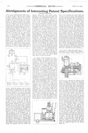
No. 10,221 : dated May 4th, 19o4,—(.1. Pilkington, of the Rex Motor Works.— The main object of this invention is to provide means whereby the engine, cran)x case, change-gear casing and operating levers for both the poSitive and slipping clutch are contained within or mounted upon the same casing, thus ensuring perfect and constant alignment of the spindle or shaft, and at the same time requiring only one setting, whereas three or more have generally been necessary hitherto. In carrying this invention into effect the casing ;AI of the engine crank gear (B) and change gear (C) is formed in one piece, with the driving shafts (E) passing through bearings formed in the engine side (al) of the casing, the internal division (a21 between the two, and the outer cover (a3: on the change gear side, while the lever (F) for operating the positive or change clutch (H) contained within is mounted in bearings formed in the casing, and therefore cannot strain the shaft (E) by reason of a difference in the alignment of the bearings. The slipping clutch (J) and the rod and lever (K) for operating same is also mounted upon the cover plate (a3) of the gear casing (A), a bracket (a4) being formed in one with the cover plate (al) upon which the operating lever (K) is mounted. In the case of the slipping clutch (11 the cone (M), which does not rotate, is provided with a ring (N), having two, three, or more pins (1)) fixed thereto, and passing through the friction cone (I), which is fixed to the driving shaft (E).