


A Controlled Differential Gear
Page 78
If you've noticed an error in this article please click here to report it so we can fix it.
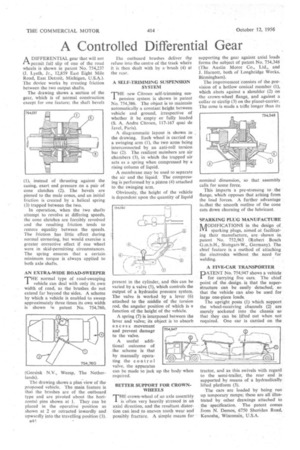
ADIFFERENTIAL gear that will not permit full slip of one of the road wheels is shown in patent No, 754,237 (J. Lyeth, Jr., 12,859 East Eight Mile Road, East Detroit, Michigan, U.S.A.). The device works by creatiug friction between the two output shafts.
The drawing shows a section of the gear, which is of normal construction except for one feature, the shaft bevels (1), instead of thrusting against the casing, exert end pressure on a pair of cone clutches (2). The bevels are pinned to the male cones, and an initial friction is created by a helical spring (3) trapped between the two.
In operation, when the two shafts attempt to revolve at differing speeds, the cone clutches are forcibly revolved arid the resulting friction tends to restore equality between the speeds. The friction has little effect during normal cornering, but would exercise a greater corrective effect if one wheel were in skid-permitting circumstances. The spring ensures that a certain. minimum torque is always applied to both axle shafts.
AN EXTRA-WIDE ROAD-SWEEPER
T" normal type of road-sweeping vehicle can deal with only its,own width of road, as the brushes do not extend far beyond the sides. A scheme by which a vehicle is enabled to sweep approximately three times its own width is shown in patent No. 754,760.
Geesink N.V., Weesp, The Netherlands).
The drawing shows a plan view of the proposed vehicle. The main feature is that the brushes are of the outboard type and are pivoted about the horizontal pins shown at I. They can be placed in the operative position as shown at 2 or retracted inwardly and upwardly into the travelling position (3). 1144 rhe outboard brushes deliver the refuse into the centre of the track where it is then dealt with by aebrush (4) at the rear.
A SELF-TRIMMING SUSPENSION SYSTEM
THE new Citroen self-trimming suspension system is shown in patent No. 754,386. The object is to maintain automatically a constant height between vehicle and ground, irrespective of whether it be empty or fully loaded (S. A. Andre Citroen, 117-167 quai de Javel, Paris).
A diagrammatic layout is shown in the drawing. Each wheel is carried ou a swinging arm (1), the two arms being interconnected by an anti-roll torsion bar (2). The resilient meinbers are air chambers (3), in which the trapped air acts as a spring when compressed by a rising column of liquid.
A membrane may be used to separate the air and the liquid. The compressing is performed by a piston (4) attached to the swinging arm.
Obviously, the height of the vehicle is dependent upon the quantity of liquid
present in the cylinder, and this can be varied by a valve (5), which controls the output of a hydraulic pressure system. The valve is worked by a lever (6) attached to the middle of the torsion rod, the angular position of which is a function of the height of the vehicle.
A spring (7) is interposed between the lever and valve; its object is to absorb excess movement and prevent damage to the valve.
A useful additional outcome of the scheme is that by manually operating the control valve, the apparatus can be made to jack up the body when required.
BETTER SUPPORT FOR CROWNWHEELS THE crown-wheel of an axle assembly
is often very heavily stressed in an axial direction, and the resultant distortion can lead to uneven tooth wear and possibly fracture. A simple means for supporting the gear against axial loads forms the subject of patent No. 754,348 (The Austin Motor Co., Ltd., and J. Harnott, both of Longbridge Works, Birmingham).
The improvement 'consists of the pro... vision of a hollow conical member (I), which abuts against a shoulder (2) on -the crown-wheel flange,. and against a collar or circlip (3) on the planet-carrier. The cone is made a trifle longer than its nominal dimension, so that assembly calls for some force.
This imparts a pre-stressing to the flange, which opposes that arising from the load forces. A further advantage is-that the smooth outline of the cone cuts down churning of the lubricant.
SPARKING PLUG MANUFACTURE AODIFICATIONS in the design of IVI sparking plugs, aimed at facilitating their manufacture, are shown in patent No. 752,963 (Robert Bosch G.m.b.H., Stuttgart-W., Germany). The chief feature is a method of attaching the electrodes without the need for welding.
A FIVE-CAR TRANSPORTER
PATENT No. 754,947 shows a vehicle for Carrying five cars. The chief point of the design is that the superstructure can be easily detached, so that the vehicle can also be used for large one-piece loads.
The upright posts (I) which support the wheel-receiving channels (2) are merely socketed into the chassis so that they can be lifted out when not required. One car is carried on the tractor, and as this swivels with regard to the semi-trailer, the rear end is supported by means of a hydraulically lifted platform (3).
The cars are loaded by being run' up temporary ramps; these are all illustrated by other drawings attached to the specification. The patent comes from N. Demos, 6750 Sheridan Road, Kenosha, Wisconsin, U.S.A.