


Abridgments of Interesting Patent Specifications.
Page 22
If you've noticed an error in this article please click here to report it so we can fix it.
Ignition Plug, Carburetter, Steering Gear, Fricticn Clutches.
No. 12,59o, dated July nth, 5904.—Ignition Plug.—Mann.—In a recess at the end of the plug a catalytic substance such as platinum black is embedded so that the gas suriounding this point is rendered more ready for ignition. Opposed to the catalytic substance is the other sparking point (d). With this arrangement the weakest spark is not found to fail to ignite the charge. To prevent sooting between the parts e and f, a series of baffles (i and it) are arranged between the shell (1) of the plug and the insulated conductor (b).
No. 9,642, dated July 22nd, 1904.— Carburetter.—Malezieux.—A flat tube (c) depends into the fuel chamber (d). Above the tube are two slots (a and b), the former open to the atmosphere and the latter open to the interior of the mixing chamber. The mixing chamber is controlled by a sliding partition (g)so that the itilot (1) may be throttled, and a valve (e) is also provided which may be used to simultaneously throttle both the slots (a and b) and the inlet (1). An air inlet valve (i) is provided which takes the form of a closed spiral spring adapted to open and admit air under the influence of auction. 'Tho flat jet of fuel sucked up the tube (c) and from the slot (b) is thoroughly atomised by the air drawn in at a, whilst the main charge enters at i.
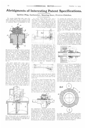
The sliding valve (e) is operated by a spring-contrclled piston which moves in a chamber in communication with the suction conduit of the engine. No. 6, t oti, dated March 23rd, 1905.— Steering Gear.—Beyer, Peacock and Co., Ltd.—The mechanism according to this invention is for steering gear of the Ackerman type. A rod (g) is pivoted to one of the arms of the steering axles and has at its free end a screw thread to receive a correspondingly threaded sleeve
(h) carrying a bevel gear wheel (j). Vertically above the bevel gear wheel (j) is a correspondingly-toothed wheel (r), hay. tag a square shank (t). The steering rod (v) Lathes a square cup (u) which engages the shank (t), so that the pinion rotates with the rod (v), but relative movement of the two parts is permitted in a vertical direction. The bevel wheel (ii is journalled in a bracket (m), pivoted at its base in a fixed bracket (o), and at its upper end in the bevelled wheel (r), which latter is in turn pivoted in a portion of the frame member (a). Rotation of the -• steering spindle rotates the bevel wheels (r and j) so that the rod (g) is made to move in one direction or the other in the sleeve (11).
No. 24,125, dated November 8th, x9o5. —Friction Clutch.--Lindsay.—The female member (7) of the clutch is made fast CO the shaft (5) and its boss receives the end of the shaft (6) so that both are kept in alignment. Fast on the shaft (6) is a ring (to) provided with a lip which is engaged by a corresponding lip (IS) on the female member so that the ring can rotate relatively to the clutch member (71, but cannot be withdrawn from it in
the longitudinal direction of the shaft. Pivoted to the ring (no) are two or more T-shaped levers (13), the longer limbs of which extend out through the male member (8), and are pivoted by links (r5) to a sliding sleeve (16). The limbs of the Tshaped members opposite those pivoted to the ring (lo) are pivoted to the male member at 14. Springs (20) arc provided for keeping the two clutch members apart. To operate the clutch the sleeve (161 is moved towards the female member so that the links (15) are brought into a more strictly radial position, which causes the levers (i3) to be rocked, and thus the male member (8) advances to engage the opposed member (7). In the drawing theclutch is shown in the engaged position. When the sleeve (16) is released thesprings (20) disengage the clutch members.
No. 1.1 J35, dated November nth,. 1904. —Friction. clutch.—Herissen.—The female member (5) is carried on one shaft, and the engagement between this and the. second shaft (4) is effected by brake shoes (x and 2). The shoes slide in radial bearings on a member (3) fast to the shaft (41, and are moved outwardly by levers (bt pivoted at 7 to tbe member (3). For operating the levers a cone, composed of four
sections (to, it, IS and 13 respectively) is. employed. Each section is movably mounted on a sleeve (9) and controlled by a spring (1.1). The sleeve (e) does not rotate with the shaft (a), and as it is advanced moves the levers (6) outwardly. The pressure of the levers on. two of the sections, say xo and 12, causes them to remain stationary, so that their springs (17) are compressed whilst the other two sections advance. The rotation of the members, however, carries the arms on to the next section so that they are further separated, and the sections (to and 121 can now move forwards whilst it and i; are held. The shoes (i and 2) are thus gradually applied by a step by step movement. For convenience, the sections are cam-shaped, so that a smooth passage is provided for the arms from one section to the other as shown in Figure 2.