


Hydraulic Control of Track-layer Steering Gear
Page 36
If you've noticed an error in this article please click here to report it so we can fix it.
A Rdsulne of Patent Specifications That Have Recently Been Published
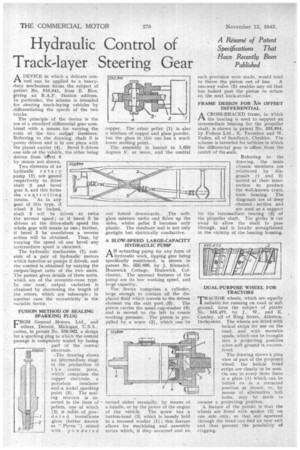
A DEVICE in which a delicate control can be applied to a heavyduty mechanism . forms the subject of patent No. 555,941, from E. Rice, giving an R.A.F. Station address. In particular, the scheme is intended , for steering track-laying vehicles by _differentiating the speeds of the two tracks.
The principle of the device is the use of a standard differential gear combined with a means for varying the ratio of the two output members. Referring to the drawing, shaft 2 is power driven and is in one piece with the planet carrier (4). Bevel 5drives one side of the vehicle, the other being
driven fromi latvel 3 by means not shown. Two elements of an hydraulic rotary pump. (1) • are geared respectively to drive shaft " 2 and bevel gear 3, and this forms the controlling means. 'As in any gear of this type, if wheel 3 . locked, shaft 5 will be driven at twice the normal speed; or if bevel 3 be driven at the drive-shaft speed the whole gear will rotate as one; further, if bevel 3 be overdriven a reverse action will be obtained. Thus, by varying the speed of, one bevel any intermediate speed is obtained.
The hydraulic Mechanism (1) consists of a pair of hydraulic motors which function as pumps if driven, and the control is, obtained by varying the output/input ratio of the two units. The patent. gives details of these units, which are of the eccentric-vane. type, In one case, output variation is obtained by shortening the length of the rotors, which are telescopic ; in another ease the eccentricity is the variable factor.
FUSION IVIETHOD.OF SEALING SPARKING PLUG .
FROM General . Motors, Ltd., and others, Detrelit,, Michigan, .U.S.A., coineS, in patent No. 556,062, a design for a sparking plug in which the central passage is completely sealed by fusing
part .of the central electrode. .
The drawing shows an intermediate stage in •the production of t h e . centre piece, which comprises the copper eleetrode, a porcelain insulator and a nickel sparking point (3). The sealing mixture is inserted in the form of pellets, one of which (2) is nade of powd e,r e d borosilicate glass (better known as "Pyrex ") mixed with powdered copper. The other pellet (1) is also a mixture of copper and glass powder, but the glass in,this one has a much lower melting point. .
The assembly is heated to 1,650 degrees F. or more, and the central
rod forced downwards. The softglass mixture melts and flows up the sides, whilst pellet 2 becomes only plastic. The resultant seal is not only gastight but electrically conductive.
A SLOW-SPEED LARGE-CAPACITY HYDRAULIC PUMP
AN actuating pump for any form of hydraulic work, tipping gear being specifically mentioned, is shown in patent No. 555,896, by J.. Kinnaird, Braiswick Cottage, .Braiswick, Colchester. The unusual features of the pump are its low working speed, and large capacity.
The, device comprises a cylinder, large enough to contain all the displaced fluid which travels to the driven element via the exit port (6). The piston carries the usual cupLwasher (4) and is moved to the left to create working pressure. The piston is propelled by a "screw (2), which can be turned either manually, by means of a handle, or by the Power of the engine of the vehicle. The screw has a button-head (3) which is loosely held in a recessed washer (1) ; this feature allows for machining and assembly errors which, if they occurred and no such provision were made, would tend
to throw -the piston out of line. A one-way valve (5) enables any oil that has leaked past the piston to return on the next back-stroke,
FRAME DESIGN FOR XN OFFSET DIFFERENTIAL
A CROSS-BRACED frame, in which Pl. the bracing is used to support an intermediate bearing for the propeller shaft, is shown in patent No, 555,894, by Fodens Ltd., E. Twemlow and W. Foden, all of Sand bach, Cheshire. The scheme is intended for vehicles in which the differential gear is offset from the centre of theiaxle.
Referring to the drawing, the main chassis members. are reinforced by diagonals (1 and 2) united at their intersection to produce the well-known cruciform bracing. The diagonals are of deep channel section and are used as a support for the intermediatebearing (3) of the propeller shaft. The girder is cut away to allow the shaft to pass through, and is locally strengthened in the vicinity of the bearing housing.
DUAL-PURPOSE WHEEL FOR TRACTORS 'TRACTOR wheels, which are equally 1 suitable for running on road or soft ground, form the subject of patent No. 555,472, by J., W., and E. Cundey, all of Ring Street, Alfreton, Derbyshire. The wheels are fitted with helical strips for use on the road, and with movable spuds, which can be brought into a projecting position when soft ground is encountered.
The drawing shows a plan view of part of the proposed wheel: the helical tread strips are clearly to be seen. On. one. in every three there is a plate (1) which, can be bolted on in a retracted position as shown; or, by means of alternative bolt
holes, may he made to assume a projecting position A feature of the patent is that the wheels are fitted with spokes (2) on one side only, so that soil squeezed through the tread can find an easy exit and thus prevent the possibility of clogging.