


t. Drivers &Mechanics
Page 19
If you've noticed an error in this article please click here to report it so we can fix it.
Light Up Your Lamps At 5.15 on Thursday ; 5.13 on Friday ; 5.11 on Saturday; 5.9 on Monday ; 5.8 on Tuesday ; 5.6 on Wednesday.
Facing Up Square Bearing-brasses.
The sender of the followiny communication has been awarded the 108. prize this week.
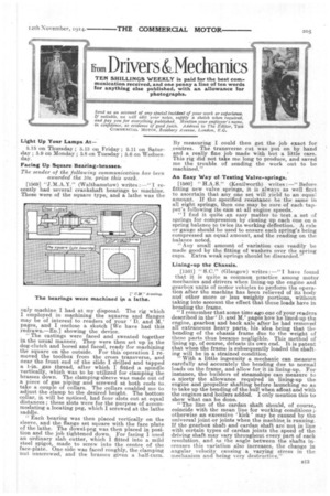
[1569] "J.M.A.Y." (Walthamstow) writes : —" I recently had several crankshaft bearings to machine. These were of the square type, and a lathe was the only machine I had at my disposal. The rig which I employed in machining the squares and flanges may be of interest to readers of your D. and M.' pages, and I enclose a sketch [We have had this redrawn.—En.] showing the device. "The castings were faced and sweated together in the usual manner. They were then set up in the dog-clutch and bored and faced, ready for machining the square on the outside. For this operation I removed the toolbox from the cross transverse, and near the front end of the slide I drilled and tapped a 1-in, gas thread, after which I fitted a spindle vertically, which was to be utilized for clamping the brasses down. The clamping-sleeve was made out of a piece of gas piping and screwed at both ends to take a couple of collars. The collars enabled me to adjust the clamp to the desired height. The bottom collar, it will be noticed, had four slots cut at equal distances ; these slots were for the purpose of accommodating a locating peg, which I screwed at the lathe saddle.
"Each bearing was then placed vertically on the sleeve, and the flange set square with the face plate of the lathe. The dowel-peg was then placed in position and the job tightened down. For facing I used an ordinary slab cutter, which I fitted into a mild steel spigot, made to screw into the centre of the face-plate. One side was faced roughly, the clamping nut unscrewed, and the brasses given a half-turn. By measuring I could then get the job exact for centres. The transverse cut was put on by hand and a really fine job made with but a little care. This rig did not take me long to produce, and saved me the trouble of sending the work out to be machined."
An Easy Way of Testing Valve-springs.
11560] `` H.A.S." (Kenilworth) writes :—" Before fitting new valve springs, it is always as well first to ascertain that any one set will yield to an equal amount. If the specified resistance be the same in all eight springs, then one may be sure of each tappet's following its cam at all engine speeds.
"I find it quite an easy matter to test a set of springs for compression by closing up each one on a spring balance to twice its working deflection. A rule or gauge should be used to ensure each spring's being compressed an equal amount, and the reading on the balance noted.
"Any small amount of variation can readily be made good by the fitting of washers over the spring cups. Extra weak springs should be discarded.'
Lining-up the Chassis.
[1561] " S.C." (Glasgow) writes : —"I have found that it is quite a, common practice among motor mechanics and drivers when lining-up the engine and gearbox units of motor vehicles to perform the operation after the machine has been relieved of its body and other more or less weighty portions, without taking into account the effect that these loads have in bending the frame. " I remember that some time ago one of your readers described in the" D. and M.' pages how he lined-up the engine, gearbox and back axle after he had removed all extraneous heavy ,parts, his idea being that the bending of the chassis frame due to the weight of these parts thus became negligible. This method of lining up, of course, defeats its own end. It is patent that when the frame is subsequently loaded the shaft. ing will be in a strained condition.
" With a little ingenuity a mechanic can measure carefully and accurately the bending due to normal loads on the frame, and allow for it in lining-up. For instance, the builders of ste.amships can measure to a nicety the allowance required in lining-up the engine and propeller shafting before launching so as to take up the bending of the hull when afloat and with the engines and boilers added. I only mention this to show what can be done.
"The line of the cardan shaft should, of course, coincide with the mean line for working conditions ;otherwise an excessive ' kick ' may be caused by the universal joint or joints when the machine is running. If the gearbox shaft and cardan shaft are not in line . with certain types of cardan joints the speed of the driving shaft may vary throughout every part of each revolution, and as the angle between the shafts increases this variation also increases, the change in angular velocity causing a varying stress in the mechanism and being very destructive."