


Power-assisted Steering Mechanism
Page 36
If you've noticed an error in this article please click here to report it so we can fix it.
POM Clayton Dewandre Co.. A Resume of Patent td., and J. Rodway, both . of Titanic Works, Lincoln, Specifications That comes, in patent No. 559,855, a design of apparatus for the servo application of power to Published the steering of a heavy vehicle. Compressed air is the medium used, but the patent is not limited in this respect. Although the draWing shows a double;• ended steering arrangement, this is purely for military purposes and forms no essential part of the invention.
In operation, the hand-wheel motion is 'transmitted to a lever (4), which opens One of the control valves (2 Or 3) according to the direction, of its rotation. Compressed air is thereby admitted to one side or the other of the servo cylinder (1), which actually moves the road wheels. A return linkage, shown generally at 5, imparts a self-closing action to the valves, and thus makes the steering progressive and proportional to road resistance. The linkage also sets up a correcting action in the servo cylinder should the road wheels be forcibly. deflected.
TWO-SPEED REVERSE IN CONSTANT-MESH GEARBOX I T is a rather difficult matter to incorporate a reverse drive in a constantmesh gearbox, and patent No. 559,195, shows a favourable method of doing it. The patentees are FodenS, Ltd., W. Foden and E. Twemlow, all of Sandbach, Cheshire, The gearbox itself formed the subject of patent No. , 522,260.
The large gear 3 is free on the driven shaft (4), but can be clutched thereto by moving a sliding dog (2) to the right. Gear 3 also drives a broad idler (7) which is in constant mesh with a
sliding idler (1). The latter idler meshes with teeth cut around the periphery of the dog-clutch. (2) which is part of the output shaft.
For forward drive, pinion 6 drives gear 3 which is then clutched to the output shaft ; for reverse drive, the power travels via gear 3, idler 7, idler 1 and the dog-clutch gear (2). Gear 2 is of smaller diameter -than gear 3 so that it just clears the teeth on the broad idler (7).
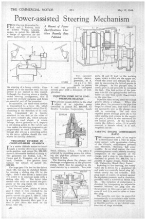
The auxiliary gcarliox, shown, generally, dt 5, imparts two speeds to 'pinion provides a two-speed reverse gear with a minimum of complication. 6 and thus INJECTION PUMP WITH LINE. PRESSURE RELEASE rTI prevent nozzle dribble is the chief L object of an injection pump described in patent No. 559,703, by I3endix Aviation Corporation, South Bend, Indiana, U.S.A. The effect is
achieved by providing means tot releasing the pipe-line pressure after, each injection of fuel.
The drawing shows the plunger and discharge arrangements of the proposed pump, which may be operated in the usual manner by a camshaft. Two inlet ports (2 and 3) lead to the working space, which is filled .via the upper one, whilst the lower one releases the pressure by uncovering the helical groove in the plunger. As the plunger rises, it covers port 2 and proceeds to compress the fuel. The first action of the pressure.is to lift the spring-loaded delivery valve (1) and thus apply the.pressure to the pipe line.
Injection then occurs until the helical groove effects a release. When this takes place, the pressure in the pipe line drops to almost zero, but valve 1 does not necessarily seat, as the plunger may still be ascending. The fuel then expelled passes through ports (5) in the valve seating and returns to the supply via port 4, which is also uncovered by the helical groove. At the top-deadcentre the delivery valve (1) is gently reseated, a feature which, it is said, lengthens its life.
VARYING ENGINE COMPRESSION ,RATIO
THETompression ratio of an engine is compression ermined with a view to max.iH mum output; with progressive closing of the thiottle, compression pressure and, therefore, efficiency, fall away
. rapidly. In an ideal "engine, the corn: . pression pressure would remain constarkt irrespective of the quantity of the charge, and a step in this direction is disclosed in patent No. 559,710, by a pioneer of engine design, Frank Aspin.
" 149. Walmersley Road, Bury, Lancs. Referring to the drawing, the rotary valve (3) is driven bY a gearwheel (6) and seats in a conically bored plug (4), which closely fits the cylinder. This plug must, of course, be secured against the explosion pressure, and is, therefore, provided with a screwed-on thrust ring (5). The variation of compression is obtained by interposing an adjustable member between the plug and the thrust-plate; in this case a pair of face. cams(1 and 2) is_used to raise or lower the plug. The movable cam may be controllod automatically in accordance with intake suction, aogine speed, cylinder pressure, or throttle position, or any desired combination of they variables.