


Controlling Injection Pressure
Page 48
If you've noticed an error in this article please click here to report it so we can fix it.
A Résumé of Recently Pubfished Patent Specifications
ASCHEME by which, it is claimed, the injection pressure of an oil engine can be controlled by a simple adjustment on the pump, is described in patent No. 502,663, by A. Kravits and A. Nemes, I. Tigris-u. 41, Budapest, Hungary. In this design, the pump is driven via a coil-spring coupling (I). The camshaft carries four normal cams for the operation of the plungers, an additional cam (3) being provided. This cam is approximately square, and is acted upon by a tappet, loaded by a powerful spring (2). The action appears to be to cause the shaft, at low speeds, momentarily to come to a standstill, whilst the coupling stores enough energy to overcome the spring (2); this having occurred, the pump then accelerates violently and gives the equivalent of high-speed injection.
A Dual-purpose Piston Ring.
APISTON ring which will function both as a sealing ring and as a scraper, is shown in patent No. 502,695, by A. Taub and Vauxhall Motors, Ltd., Luton. Referring to the accompanying drawing, it will be seen that this ring is cylindrical for about one-third of its height, as shown at 2, the remainder (1) being slightly conical. The inner face of the ring is shaped so as to cause a twisting force when the ring is in place, so that it takes up a position as shown, somewhat exaggerated. Other rings, of a more normal type, can be used in conjunction with this special design.
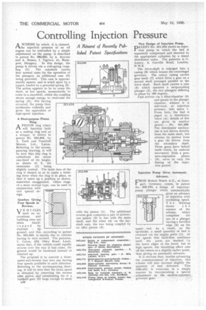
Gearbox Giving Four Speeds in Reverse.
11,J E H I CLES V used on ex• cavations and building sites are often
handicapped by churned up ground, and this, according to patent No. 502,563, is mainly due to vehicles having to turn around. The patentee, C. Caton, 423, Otley Road, Leeds, states that, if the vehicle could rapidly reverse over the way it had come, the ground would be hardened instead of churned up.
The proposal is to convert a threespeed-and-reverse box into one having four speeds available in each direction. Referring to the accompanying drawing, it will be seen that the extra speed is obtained by removing the reverse idler pinion and substituting for it a layshaft gear (5) large enough to mesh with the pinion (1). The additional reverse guar comprises a pair of pinions; one pinion (2) in line with the main shaft, and the other (4) on the layshaft axis, the two being coupled by an idler pinion (3). New Design of Injection Pump. PATENT No. 501,633 shows an injection pump in which the fuel is separately compressed and directed to the appropriate cylinders by a timed distributor valve. The patentee is G. Amery, 3, Greville Road, London, N.W.6,
The drive-shaft is enlarged into a casing (8) which houses the centrifugal governor. The rotary casing carries gear teeth (7) which drive a gear on a second shaft arranged parallel to the drive shaft. Each shaft carries a cam (6) which operates a reciprocating plunger (2), the two plungers differing in phase by 180 degrees.
Fuel arrives via a filter-chamber (9) and passes to the plunger chamber, whence it is delivered, at injection pressure, into space 1. From here, the fuel is piped to a distributor valve (4); details of this are given in another patent — No. 501,588. The distributor mechanism is not driven directly from the main shaft, but obtains its motion from a gear (5) driven from the secondary shaft. These gears have helical teeth which, by endwise movement from a pressure-responsive piston (3), serve to vary the timing of the injection period.
Injection Pump Gives Automatic Advance.
FROM Robert Bosch A.G., of Stuttgart, Germany, comes, in patent No. 502,723, a design of injectionpump plunger which automatically gives an advance of injection with increasing speed. T h e drawing
shows the essence of the scheme, which comprises the use of a plunger having a bevelled edge (2) on the upper end. As a result, on the up-stroke, a small quantity of fuel is returned via the supply ports (1). At low speeds this back-flow continues until the ports are masked by the lower edges of the bevel, but at high speeds, the throttling effect cuts off the return at a slightly earlier point, thus giving an automatic advance.
It is obvious that, besides advancing the commencement of injection, this scheme will also increase slightly the quantity of fuel delivered. This difficulty is overcome in a simple manner by incorporating aspecial adjustment in the suction-operated governor gear.