A Short-wheelbase Six-wheeler
Page 68

If you've noticed an error in this article please click here to report it so we can fix it.
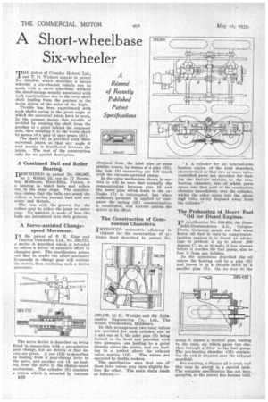
THE names of Crossley Motors, Ltd., and T. D. Wishart appear in patent No, 389,900, which describes a means whereby a six-wheeled vehicle can be made with a short wheelbase without the disadvantage usually associated with such constructions due to the very short shaft leading from the gearbox to the worm drives of the axles of the bogie.
Trouble has been experienced with such shafts owing to the great angle at which the universal joints have to work. In the present design this trouble is avoided by running the shaft from the gearbox to a point behind the rearmost axle, then coupling it to the worm shaft by means of a pair of spur gears (Bi). The shaft (B) is provided with three universal joints, so that any angle it may assume is distributed between the joints. The rest of the construction calls for no special description.
A Combined Ball and Roller Bearing.
DESCRIBED in patent No. 390,067, by J. KaHai, 15, rue de 17 Novembre, Mulhouse, Haut-Rhin, France, is a bearing in which balls and rollers run in the same rings. The specification claims that the balls can assist the rollers in bearing journal load and can resist end thrusts.
The race with the groove for the rollers may be either the inner or outer ring. No mention is made of how the balls are introduced into their grooves.
A Servo-assisted Changespeed Movement.
IN the patent of S. R. Edge and
Clayton Dewandie, Ltd.; No. 389,775. a device is described which is intended to relieve a driver of excessive effort in changing gear. The specification points out that in traffic the effort necessary frequently to change gear will overtax the driver, thus rendering such a device necessary.
The servo device is described as being fitted in connection with a pre-selective gear change, but no detaiLs of that device are given. A rod (12) is described as leading from a gear-change lever to the servo, and another rod (4) as leading from the servo to the change-speed mechanism. The cylinder (7) contains a piston which is actuated by vacuum 3350 obtained from the inlet pipe or some similar source, by means of a pipe (15), the link (8) connecting the bell crank with the vacuum-operated piston.
In the valve mechanism shown in section it will be seen that normally the communication between pipe 15 and the lower -pipe which leads to the cylinder (7) is interrupted, but when sufficient pressure is applied tocompress the spring (25) communication is established, and vacemn assists the driver in his effort.
888,789, by H. Weslake and the Antemotive Engineering Co., Ltd., The Green, Twickenham, Middlesex.
In this arrangement two inlet valves are provided for each cylinder, one at 3 and one at 5, the inlet pipe (8) being formed in the head and provided with two passages, one leading to a point directly above the piston, and one leading to a pocket above the exhaust
valve seating (12). The valves are operated by double rockers. The specification says that one of these inlet valves may open slightly before the other. The main claim reads RS follows:— "1. A cylinder for an internal-combustion engine of the kind described, characterized in that two or more valvecontrolled ports are provided for feeding the fuel-air mixture to the combustion chamber, one of which ports opens into that part of the combustion chamber immediately over the cylinder, whilst the other opens into the aforesaid valve cavity disposed away from the cylinder."
The Preheating of Heavy Fuel "Oil for Diesel Engines.
IN specification No. 389,458, the Hum boldt-Deutzmotoren A.G., CologneDents, Germany, points out that when heavy oil fuel is used in compressionignition engines it is found an advantage to preheat it up to about 200 degrees C., so as to make it less viscous before it reaches, the fuel pump, also to free it from gas bubbles. In the apparatus described the MI enters the heating coil by a pipe (5) and leaves it in a thinner state by a smaller pipe (7). On its way to the
pump it passes a vertical pipe, leading to the tank, up which gases can rise, then through a filter to the fuel pump. The pre-heating chamber (13) containing the coil is situated near the exhaust manifold.
For starting, a thinner qil is used, and this may be storgg in a special tank. The complete specification has not been accepted, so the patent has become void.


