


( THE ORE of THE
Page 14
Page 15
Page 16
Page 17
Page 18
If you've noticed an error in this article please click here to report it so we can fix it.
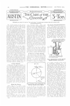
GIASSIS
Although, as a rule, it is well to " let well alone." it needs care to ensure that all is always well.
The general purpose of the present series is set out at some length in the early Editorial pages of the present issue, and we refer our readers to that exposition of our present object.
We may content ourselves, therefore, by way of introduction to this, the first of a new and important series of descriptive and illustrated articles, by repeating that it is our desire, by means of carefully-prepared illustrations, and of letterpress compiled with equal forethought, to assist the manufacturer and the designer to secure, by systematic inspection and adjustment, and by periodic lubrication, that amount of care for the chassis as a whole which will secure the maximum of efficiency and the longest effective life of the machihe after it has left the manufacturer's or the agent's hands.
We have chosen for the first subject the Austin 2-3-ton model, as it is called— a machine unique in design and replete with evidence of care expended during its conception and &eduction. We have written of, and illustrated lavishly, its many structural peculiarities in the past. It is not part of our programme, in the present series, to place on record an account of • the distinctive constructional features per se of various chassis. We wish broadly to confine ourselves to indicating the reasons which have prompted the designers to embody certain special means of adjustment and facilities for lubrication, and to suggest how and ellen these should be carefully used,
A Low Chassis.
Briefly put, the type of machine we are considering is distinguished in many ways, but principally by a desire on the port of its sponsors to provide a chassis which shall present an unusually low loading line, and which, in respect of its final drive, should embody the admitted advantages of both chain and enclesed-gear classes of final reductions.
It will snit our purpose best to consider the intended adjustments of the chassis as a whole if we divide it into a number of units, and perhaps the best way to do this is to suggest for separate consideration: the engine and clutch gear; the gearbox; the final drive; the steering-gear and control mechanism ; the springs, axles and wheels; and the brakes.
About the Valves.
Those parts of the Austin engine which are likely to call for occasional adjustment, and by that we do not sugeest those alterations which should only he necessary when the ermine is "taken down " for a refit, are : the valve gear and its setting; the carburetter; the magneto and ignition outfit; and the primp packing.
It is advisable that all the valves should be inspected, and the exhaust valves, at any rate, ground in once in le2 every thousand miles. , After such grinding, it will be found that mushroom valves invariably rub themselves in a little bit, thus further lowering their spindles on to the tappets. It will be wise, therefore, some little while after any such grinding, to inspect the clearance between the valve stem and tappet, and to see that this is sufficient to allow a thin piece of notepaper or its equivalent to be passed between the two parts. The method of lifting the valves and detaching the springs is not, of course, an adjustment, and, moreover, it is an operation which is hie/viably understuod by those who have had anything to do with petrol engines of any kind. The adjostment of the tappets is a simple and obvious procedure, and is effected by screwing the nut and locknut, which will be found on ouch one, in the desired direction.
Neglect to see that there is sufficient clearance between the valve stem and tappet. or to insure that the valve seats or pockets have been properly cleaned, will result in a lack of compression after this grinding operation has taken place.
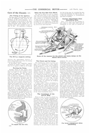
A Word as to Valve Setting.
The actual setting of the valves themselves is net an operation which we can riehtly include in the list of actual adjustments. As, however, circumstances may arise necessitating the deliberate derangement of the valve timing, it may be useful to indicate the standard set tine for the 20 h.p. lorry engine. The smell diagram which we reproduce of the valve setting, taken_ in conjunction with the marks on the flywheel rim showing the top centres for the various cranks, ehould render it an easy matter for the camshaft gear wheels to be so engaged as to give the valve openings shown. The accuracy of the earn machining will insure the correct closings if the opening.s be set properly,
The Austin-Claudel Carburetter.
Now, with regard to the carburetter, the standard fitting for the Austin chassis is known as the Austin-Claudel, and one of our illustrations herewith shows an example in an imaginary sectional view. Carburetter troubles, of course, are nothing like so frequent as they were in earlier days, and, as a general rule, it may be taken for granted that interference with the jet, with the float and its counter-weights, or with the needle should be avoided. The needle, how ever is likely, especially if dirty petrol be accidentally employed nowand again, to need occasional grinding in, to insure proper seating and shutting off under the action of the float, and this in spite of the fact that adequate filters are provided in the petrol-supply system. It is advisable to clean these last-men. tioned at least once a week.
We could, of course, write chapters on the proper adjustment of carburetters in general, but we must properly confine ourselves, irk the present instance, to a few remarks as to adjustments which may be normally eeceseary in the particular case of the Austin equipment. We cannot do better in this respect than quote what "The Austin Advocate "the excellent house journal of the Austin Motor Co.—has to say on this point, and this extract should be read in conjunction with the carburetter illustration to which we have already referred :
"The air screw (A), situated directly above the air intake, is for the adjustment of the final amount of air passing through the mixture chamber with the threttle closed. It is desirable to keep this air screw unit as far as possible consistent with slow running, when there is no load on the engine. Should it be found necessary to adjust the air screw right in to enable the motor to turn very shewly, then the small ley-pas screw, which is situated directle re-r
t he air screw, should be lightly screwed out; at the same time, the air e.clew (A) should be withdrawn a proportionate amount, in order to avoid a heavier consumption of spirit than is necessary at low speeds. "To adjust the throttle travel, a stop screw, which will he found near the float chamber, is normally set for slow running, but this can be adjusted to increase the amount of gas passing to the engine, or to cut it off completely, by setting the screw inwards or vice verso. The other stop screw on the throttle is set for a full opening and should not be altered. If it be found absolutely necessary to alter the richness of the mixture supplied to the carburetter, this can be done in two ways, either by adjusting the height of petrol in the jet, or by tug the bore of the latter.
When to Alter the Jet—Only for Special Circumstances.
" It should only be necessary to alter the size of the jet: (a) when maximum yeewer regardless of consumption is required, when a larger jet with a slightly luwer level may be tried; (b) when the is to operate in a tropical or very. hot country, when a smaller jet may be ti led ; (c) when it is desired to i un oil benzoic ; (d) when a better consumption than what may be normally expected is sought for at the expense of a slight dee, ease in power. '• The height of the petrol within the float chamber can be adjusted by altering the position of the collar on the cutoff needle. This is only a tight fit, and can be gently driven up to decrease and down to increase the height of the pt.trol in the chamber." The fitting of a new float and its adjustment for weight, in the event of puncturing or other damage to the old one, is a replacement and not an adjust. nt, and, moreover, it is one which will pi ,-sent little difficulty to the majority of Oti eeaders.
The Much-abused Magneto. The Wear on the Make-and-Break.
Few components of a complete engine have in the past been more abused by maladjustment than the ignition installation. Nowadays all modern exampties consist of a high-tension magneto, with occasional dual systems to facilitate starting. Our advice again, in the ease of the magneto, which is part of the dual system, on the Austin, is to leave it alone, unless the circumstances be exceptional, and unless the would-be adjuster is absolutely convinced that this is the part that is responsible for somo temporary disablement. One of the most likely things which may happen and which may necessitate attention is that the platinum points of the make-and-break mechanism may become too far apart for some reason, with the result that a weak spark will be given at. low speeds. Maladjustment here alters the timing of the sparking, because the break will occur at some point when the current generated to the armature is not at its maximum strength. This is most noticeable at low speeds. To put the matter right, the adjustable platinumtipped screw should be so regulated that the gange or feeler on the magneto spanner, which is supplied with the ordinary tool kit, can just be inserted between the platinum points. If the points awe ont of order, owing to burning or wear, they should be very carefully filed flat with the finest available file.
The Timing of the Ignition.
The spur gear in the magneto ease need never be tampered with, short of die• sembling of the whole magneto. As a general guide to the setting of the magneto relatively to the engine cycle, the make-and-break points should be just opening when each cylinder in turn is due to fire. We reproduce a diagram showing the approximate interval at which this should occur when the timing kver is fully advanced. If the plugs, upon inspettion, appear doubtful in regard to their gaps they may be set again to 1-50th in. or .5 mm.
Packing the Pump.
Another detail on the engine which necessarily requires to be looked at front time to time is the packing gland around the pump, and 'this should be
kept reasonably tight.. If adjustment fails to effect the stoppage of any leakage, fresh packing is necessary, and this may be effectedby slacking back the locking nut and theinut a the gland. The bress sleeve, which comes into view when the nut is undone, should then be slacked and pushed back as far as possible. The packing can then be removed, and fresh asbestos string, soaked in lubricating oil or hot tallow fat, can be wound on the spindle and forced back into position in sufficient quantity.
The gland must not be peaked too full, and it should be possible to insert the sleeve one-sixteenth of an inch into it before it touches the packing. The gland will be packed sufficiently tight when, if the nut. be screwed down, half the sleeve will have entered the gland.
When the Pan Belt Gets Slack, No wear is likely to occur in Courice
lion with other parts of the cooling system, with the exception that the fan belt may require to be tightened from tie to time; it may need a new fastening, or a length to be cut out of it. The special provision for easy tightening of the belt on the Austin fan drive is well illustrated by one of our small sketches.
The Clutch and Its Lining.
The Austin lorry cluteh is of the cone type, and a Haybestoe or other similar lining is attached to the inner periphery of the flywheel in sections, the engaging member consisting of a pressed-steel disc properly shaped. There is no actual adjustment for the clutch spring ; if greater pressure is required from it, a stronger spring is supplied. If, however, slipping becomes incurable by the ordinary means of adjustment which is described under the heading " When the Clutch Wears," on page 42a, it may be found that the glaze on the fabric sections may be remedied by scraping or slightly filing them.
It may, under certain circumstances, be advisable Co remove the sections of fabric and their metal mountings, and this is achieved with the aid of a small special lever, whirl, is supplied with each chassis for this purpose. An illustration of thie tool is included with our drawing of the clutch mechanism above.
The Importance of the Clutch Stop.
Next in order we come to a brief coneideration of the proper adjustment of the clutch stop—a most important component which considerably aids satisfactory gear changing. The position of the clutch stop is indicated on certain of our drawings. The extent to which this fitting comes into attion depends upon the distance through which the clutch pedal is depressed. When attempting to secure better adjustment of it, itis perhaps best to remove the footboards and to watch the action of the stop as it slows the clutch when the pedal is depressed. In -hanging down gears the clutch stop heed not come into action at all. As the clutch wears and the clearance provided on the pedal-operating gear has to be adjusted, the movable portion of the stop should he screwed away from the gearbox towards the clutch by a like amount. This is simply effected by unscrewing the set pin, which enters into the slot in the stop, by screwing the stop round anti-clockwise for half a turn, or a full one, according to circumstances, and then re-locking.
Gearbox Adjustments when Assembling Only.
Now, with regard to the gearbox itself, there is very little that need be considered in the light of normal ad e-TN juetment for wear. Once the selector mechanism and the sliding gears are relatively located during assembly, and once the bevel gears are placed correctly in angular relationship and at the proper depth of tooth meshing, there should be no need to interfere with the moans of alteration that are provided until the time arrives for dissembling the box again and replacing any worn or broken pelts. Nevertheless, there are adjustments in the Austin lorry change-speed box which are plainly visible, and of which it may be wise, therefore, to indicate the use, if only to obviate any unauthorized and unnecessary interference with any of them. Where the propeller shafts emerge at angles from the rear of the gearbox proper, each will be eeen to be provided with a pair of slotted adjustment nuts. The larger of each pair—that one which is nearest to the gearbox—is adjusted by screwing in or out when the gears are being assembled, in order to insure the proper depth of meshing between crown bevel and wheel. Once settled, there is obviously very little likelihood indeed of any alteration being necessary. This is, therefore, locked in position, once and for all, after assembly.
The smeller slotted nut is to enable the thrust licsia the bevel pinion to be corectely taken up by the ball thrust bearjug inside, to which this duty is allocated, This is also an adjustment which is attended to during the assembly of the box. Subsequent use of it should only b-seecessary in the infrequcut event of the hall thrust bearing afuresaid wearing down or slacking back to any extent. These are the reasons for these two adjusiments, and we give them primarily to warn owners and mechanics not to attempt to interfere with them unless they are thoroughly persuaded as to the need for such change. These gearbox bearings have incorporated with them spring
adjustment needs no explanation.
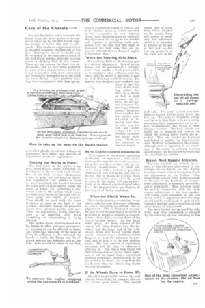
Keeping the Bevels in Place.
The final drive on the Austin is by twin bevel-driven shafts eeparatelv to bevel gears on the two back road wheels. One of our little circular illustrations eerves to point out the pairs of bevelgear adjustment nuts, similar to those we have described, but located towards the after ends of these shafts, where the drive is taken via cardan-block universal joints to the casings. which house the final bevel drives on the road wheels. 'These pairs are similar in purpose. They should be used with the same hesitancy as those at the back of the gearbox; the front ends of the propeller shafts have spherical joints, with provisiou for adjustment, which, however, need to be employed only when assembling or reassembling is beieg effected.
The cardan shafts have hardened sliding blocks to allow universal movement ; no adjustment can be effected to these, but, after long intervals, if the wear on them be sufficient to be indicated by knock or rattle, the blocks may be replaced without any difficulty and at low cost. Care should be taken to see that, when itbecomes necessary to remove any of the leather shoes or eovers provided by the constructor to cover exposed joints, thew should be properly replaced. Manufaneurers do not go to the troade and expense of providing such safeguards with the idea that they shall be discarded the first time they are removed, although this evident* of neglect is freceeentiy seen.
When the Steering Gets Slack.
We need say little of the steering gear inr sspece of adjustment, It is of special design, and the. pro-vision of a. complete worn, wheel enablesa fresh portion of it to be employed when sufficient wear has taken place to render it desirable to take up slack that, may result therefrom. The housing is so designed as to render it possible to alter the rake of the steering pillar, but this, as a matter ef fact, is kept constant on the lorry for all normal purposes. The steering joints are amply protected from weather, hut the leather cases should he removed from time to time and the ball and socket adjustments thereon examined for undue slackness, which can be corrected by obvious means.
controlled glands, to obviate leakage of As to Engine-control Adjustment. lubricant; their object and method of
With regard to the engine-controlling
mechanism, we reproduce a sketch showing the adjnetment to the accelerator pedal—we. have written fully of carburetter ntedifirations. A small setscrew fitted with a lot:kind is provided immediately over this pedal, and it is intended that it should be screwed down to snch an extent that, when the pedal is released, the engiue will run satisfactorily at its slowestpractical speed when free. Its employment is not likely to be tile subject of faulty regulation.
When the Clutch Wears In.
The cluteheeperating mechanism is one which calls for some attention, although, of course', involving no difficult feat of adjustment-. This is illustrated on page 42, and it will be seen that a, set-screw is provided to render it possible to counteract the effect of the wearing down of the clutch friction snrface. As the latter takes place, the male member of the eluteh will enter further into the flywheel, and thelonger end of the withdrawal lever will travel further backwards. It is necees.ary, therefore, as this happens, to back the set-screw in cluesteen and to lOCk it in its new position again. The exact amount of adjustment necessary will be clear to whoever is effecting it. The clutch stop limits the full downward travel of the clutch pedal, and itwill be found that aconvenient pus-Aloe as between these two will be for the pedal to be about 4 in. away from the footboards when the clutch stop checks further movement.
If the Wheels Have to Come Off.
Should it be desired to remove the road wheels, far re-tiring for example, this can
lei effected quite easily. The special
stub axle. The usual loeknut and enddistance washer will he found inside the hub cap. The wear of the bushes, either endwise or in their bore, will, as is usual, necessitate their replacement, or, in certain circumstances, the fitting of new distance washers. The back wheels are pulled up on tapered huh centres to which the driving bevel wheels are attached. They are located on keyways and locked in position by big-diameter -nuts. Endwise adjustment of the wheels, although such an operations is notnocessary in the course of ordinary running maintenance, can be effected by replacing the end-distance waehere.
Brakes Need Regular Attention.
We may conclude our remarks in respect of the effective adjnstment of the various chasnis details on the Austin two-three-limner with a few paints about theacljustment of the brakes. The pedal brake acts on a big drum mounded on the side of the flywheel. A thumbscrew adjustment is unusually accessible, and it locks itself, This, however, must be used in couj unction with the step screw ; adjustment of the. two together will insure repsal alteration on the two shoes, and it is important that this stop should not be. overlooked, in spite of the tempting position and construction elf the other means of adjustment.
The back brakes are operated by side lever, and their adjustment is effected by the screwing up and Mocking of the
main pull rod at the side of the frame. This van bo bolt illustrated by reference to the special drawing of it which we reproduce on the previous page.
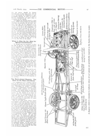
Where to Od and When.
Wc do not know that we reed say a very great deal in respect of the proper aed systematic lubrication of this chas. sic. We would prefer to rely upon the special diagrammatic oiling sketch which we have prepared, and which we include on page 41. The Austin CO. deserves great praise, not only for the care with which it endeavours to insist upon proper lubrication of its chassis details, but also for the many excellent little brochures which, reprinted from " The Austin Advocate," it issues to owners of its machines in respect of adjustment and care of the chassis.
Lubricating instructions are issued with each type of chassis, and perhaps, therefore, in these circumstances, it will suffice if we indicate broadly the lubrication which should be attended to daily and at other intervals. We will group them as follows: DAILY—Oil with small pump all the spring-shackle-pin lubricators; with oilcan to all brake connections ; with oilcan to all steering-gear joints; with oilcan to brake-control, clutch-control and engine-control prints; oil magneto; turn greaser* where provided on steering-gear details ; turn greasers on fan spindle, on water pump, on distributor spindle, on stub axles, on clutch centre and clutch withdrawal race; and on lout-brake shaft bearing.
EVERY 500 Altr.F.s.—L:se the grease gun on the four propeller-shaft universal joints ; ditto into bevel-gear cases on rear road wheels; fill leather covers of steering joints with grease. EVERY MOO aide caps with Yellow grease, and fill gearbox, through two openings, halfway with oil. The road springs should be taken down twice a year and the separated blades coated with white lead and tallow ; 2 oz. of white lead to a A lb. of tallow is a good proportion.
With regard to engine lubrication, the plug at the bottom of the base chamber s.muld be taken out every 1000 miles,
and all the old oil should be drained out, fresh oil being put through the combined breather and oil filler on the exhaust side or the engine. Every 5000 miles the base chamber should be taken off, and the oil pan and strainer taken down and thoroughly cleaned with petrol, all sediment in the bottom of the base chamber being similarly cleared away. The crank chamber should be kept filled up to the overflow.
The Important Engine-oil-pump Adjuster.
We illustrate the use of the small oil hand pump, with which the spring shackle pins should be lubricated daily. Another of our small circular drawings refers to a very important adjustment which, frum its unpretentious appearance is perhaps likely on occasion to be overlooked. This is a small set-screw situated immediately in front of the front cylinder. This controls the oil pressure for the engine supply. When it is necessaryto increase the oil pressure to be shown on the dashboard gauge, this should be screwed down and locked until
the desired 2 more, if the bearings be new and stiff—is shown.
One other adjustment of similar nature remains, and this controls the pressure which can be raised by the air pump to insure adequate petrol feed. This little fitting is to be found on the near-side of the engine case, and a similar set-screw to that last mentioned is provided ; it may be screwed dawn until the fuel-pressure gaug2 shows 4 lb. or there&routs.