


An Improved Self-adjusting Brake
Page 66
If you've noticed an error in this article please click here to report it so we can fix it.
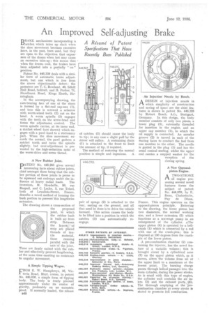
A Resume of Patent Specifications That Have Recently Been Published BDRAKE mechanisms incorporating a J.Jratchet which takes up slack when the shoe movement becomes excessive have, in the past, been used, but they are open to the objection that expansion of the drums when hot may cause an excessive take-up ; this means that when the drums cool, the brakes have been adjusted into a partially " on" position.
Patent No. 446,339 deals with a similar form of automatic brake adjustment, but one which is free from the above objectionable defect ; the patentees are T. C. Rowland, 49, Silhill Hall Road, Solihull, and H. Parker, 71, Hazelhurst Road, Kings Heath, Birmingham.
In the accompanying drawing, the cam-bearing face of one of the shoes is formed by a flat-end cap-nut (1), and into this is screwed a setscrew with worm-wheel teeth (2) cut on the head. A worm spindle (3) engages with the teeth on the screw-head and forms the adjustment control. The worm spindle carries, at its inner end, a ratchet wheel (not shown) which engages with a pawl fixed to a; stationary part. When the shoe movement exceeds the normal, the pawl gathers a ratchet tooth and turns the spindle slightly, but over-adjustment is prevented by the high-reduction ratio of the worm-drive and screw thread.
New Rubber Joint,
PATENT No. 445,255 gives several Interesting facts about rubber joints, chief amongst them being that the rubber portion of these joints is prone to be squeezed out endways under the in
fluence of heavy radial loads. The inventors, M. Houdaille, 50, rue Raspail. and C. Leder, 3, rue Trezel, both of Levallois-Perret, France, describe a novel method of forming the bush portion to prevent 'this lengthwise extension.
The drawing shows a cross-section of the proposed joint, in which the rubber bush is built up from strip. Between the layers, of strip are placed threads of tex tile material, these running parallel with the • axis Of the joint. These are firmly united with the rubber and effectively prevent lengthening, at the same time exerting no resistance to angular movement.
A Simple Tipping Wagon.
FROM E. W. Humphreys, 35, Victoria Road, Rhyl, comes, in patent No. 446,030, a simple form of tipping body. The body is freely pivoted approximately under its centre of gravity, preferably on an eccentric pivot. If normally loaded, the release
B4.8 of catches (3) should cause the body to tip ; in any case a slight pull by the driver will suffice. A restraining chain (1) is attached to the front to limit the amount of tip, if required.
The method of restoring the normal position is simple and ingenious. A pair of sprags (2) is attached to the rear, resting on the ground, and all that need be done is to drive the vehicle forward. This action causes the body to be lifted into a position in which the catches (3) can automatically reengage. Aix Injection Nozzle by Bosch.
ADESIGN of injection nozzle in which simplicity of construction and saving of space are the chief features is shown in patent No. 446,325 by Robert Bosch, A.G., Stuttgart, Germany. In this design, the body member consists of only two pieces, a lower plug (3), externally threaded for insertion in the engine, and an upper cap member (1), to which the oil supply is connected. An annular groove (2) is turned in each of the mating faces to conduct the fuel from one member to the other. The needle is guided in the plug (3) and has the usual conical seating, whilst the upper end carries a stepped washer for the reception of the closing spring.
A New Opposedpiston Engine.
A TWO-STROKE rt oil engine possessing several novel features forms the subject of patent No. 446,070, by E. Reno, Chabreloche, Puy de Dome, France. This engine operates on the opposed-piston principle. Referring to the drawing, the lower piston has two diameters, the normal working size, and a lower extension (5) which functions as a scavenge pump in an enlargement of the cylinder. *The upper piston (4) is operated by a bellcrank (1) which is connected by a rod with one of the crank-pins ; this is disposed at 180 degrees from the crankpin of the lower piston.
A pre-combustion chamber (2) containing the injector, has the novel feature of a variable volume ; this is brought about by a cylindrical nose (7) on the upper piston which, as it moves, alters the volume from nil at the upper limit to a maximum at the lowest point. The burning charge passes through helical passages into the main cylinder, during the power stroke. As is usual with this type of engine, the cylinder wall contains the air inlets (3) and the exhaust port: (6); The thorough emptying of the -precombustion chamber at every stroke is stated to promote full combustion.