


FACTORS WHICH AID IASSIS MAINTENANCE.
Page 54
Page 55
Page 56
If you've noticed an error in this article please click here to report it so we can fix it.
DURING the past decade the development of road transport has been extraordinarily rapid—far more rapid, in fact, than even the most sanguine prophets would have dared to predict at the close of the war (in 1918). The craving by everybody for a better general road performance has led to an allround improvement in every major component used in the make-up of a chassis (we propose to deal with the chassis only in this article), but it appears, at any rate on the surface of things, that improvement of the components, each and separately, has been so intensive that in dealing with them they have been treated as components only, and not considered in their relation to the complete chassis. This is a rather sweeping statement, but that it is logical can easily be appreciated by anyone who takes the trouble critically to inspect any one of a number of presentday chassis.
Take the case of the power unit, for example. In a good many instances the clutch and gearbox are mounted unitwise with the engine and are thus eligible for inclusion in the phrase "the power unit." The average engine, as a smooth-running and silent producer of power, is nowadays inordinately good, reliable and economical in fuel. Clutches are also remarkably sweet in action and very reliable, whilst any really modern gearbox with ground gears and well-supported shafts will often outlast the rest of the chassis before overhaul becomes necessary. But in such a simple matter as lubrication we find that the engine is replenished from one orifice and the gearbox from another (often very inaccessible), whilst the clutchwithdrawal race and—in certain types—the dutch spigot each has its own particular place for attention, either with an oilcan or grease gun.
• This is not all, though, for dotted all over the whole unit can be found that device—often considered the last word—the grease nipple—on the fan spindle, the auxiliary-drive spindle, the water pump, clutch and brake pedals, gear controls, etc., and yet within a few inches there is a circulating supply of two or three gallons of oil. We can only repeat what has already been said; components, separate and individual, may be bolted together, but are nevertheless as distinct from one another as if they belonged to separate chassis.
Now, it is quite easy to condemn any attempt to alter such a state of affairs by saying that further complication (a most undesirable thing) is bound to ensue. A little reflection, however, will show that this is not by any means a sinP qua non; indeed, quite the reverse might be the case, especially if the design of a completely new chassis could be started.
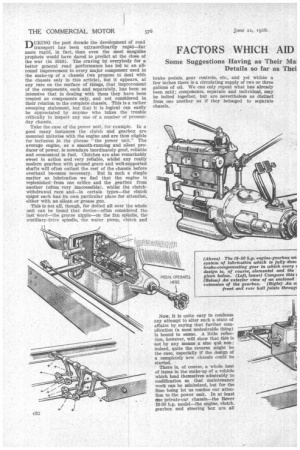
There is, of course, a whole host of items in the make-up of a vehicle which lend themselves admirably to modification so that maintenance work can be minimized, but for the time being let us confine our attention to the power unit. In at least one private-car chassis—the Rover 16-50 h.p. model—the engine, clutch. gearbox and steering box are all
lubricated from the oil in the engine sump, which is circulated under pressure by a pump. A sketch of the arrangement of this unit and the circuit of the oil is included in the illustrations ; they show quite clearly how the system operates and how all possibility of the circulation of gen. chippings (from the gearbox) is negatived by the inclusion of really sensible filters.
That the system works, and works well, is obvious to anyone who is at all familiar with Rover cars, for in the hands of the ordinary ownerdriver, Who really knows very little indeed about the internal details of his car, and often cares less, no lubrication troubles whatever have been experienced.
The foregoing description of the Rover system has merely been included to show what can be done in the direction of unification, without involving a design that is either unsound or unreliable in use. Imagine how easy it is, for instance, further to increase the usefulness of the engine-lubrication system, by arranging the clutch and brake pedals and their attendant rods to be operated from the unit, with the shaft for
each pedal passing through the casing which virtually forms the sump for the whole unit. Oil flung up by the flywheel can be used adequately to lubricate these components, whilst it is quite possible to form the brake-compensating gear unitwise with the gearbox and in communication with the oil therein.
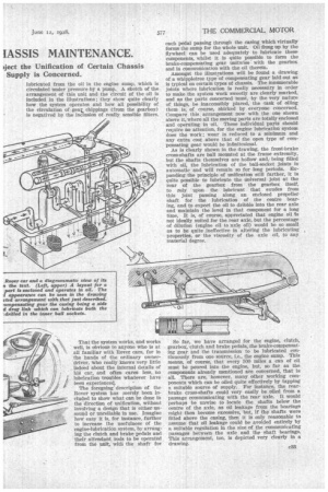
Amongst the illustrations will be found a drawing of a whippletree type of compensating gear laid out as is typical on certain types of chassis. The innumerable joints where lubrication is really necessary in order to make the system work sweetly are clearly marked, and as the parts concerned must, by the very nature of things, be inaccessibly placed, the •task of oiling them is, of course, shirked by everyone concerned. Compare this arrangement now with the one shown above it, where all the moving parts are totally enclosed and operating in oil. These individual parts should require no attention, for the engine lubrication system does the work ; wear is reduced to a minimum and any extra cost above that of the open type of compensating gear would be infinitesimal.
As is clearly shown in the drawing, the front-brake cross-shafts are ball mounted at the frame extremity, but the shafts themselves are hollow and,. being filled with oil, the lubrication of the ball-socket joints is automatic and will remain so for long periods. Expanding the principle of unification still farther, it is quite possible to lubricate the universal joint at the rear of the gearbox from the gearbox itself, to rely 'upon the lubricant that exudes from this joint passing along an enclosed propeller shaft for the lubrication of the centre bearing, and to expect the oil to dribble into the rear axle and maintain the level in that component for a long time. It is, of course, appreciated that engine oil Is not ideally suited for the rear axle, but the percentage of dilution (engine oil to axle oil) would be so small as to be quite ineffective in altering the lubricating properties, or the viscosity of the axle oil, to any material degree.
So far, we have arranged for the engine, clutch, gearbox, clutch and brake pedals, the brake-compensating gear and the transmission to be lubricated continuously from one source, i.e., the engine sump. This means, of course, that every 500 miles a can of oil must be poured into the engine, but, so far as the components already mentioned are concerned, that is all. There are, however, many other working components which can be oiled quite effectively by tapping a suitable source of supply. For instance, the rearbrake cross-shafts could very easily be oiled from a passage communicating with the rear axle. It would perhaps be unwise to locate the shafts below the centre of the axle, as oil leakage from the bearings might then become excessive, but, if the shafts were fitted above the casing, then it is only reasonable to assume that oil leakage could be avoided entirely by a suitable regulation in the size of the communicating passages between the axle and the shaft bearings. This arrangement, too, is depicted very clearly in a drawing.
The principle of oiling various chassis bearings from oil reservoirs is, of course, quite an old idea. It is, however, a very effectiva way. The brake crossshafts, for example, seem literally to ask to be filled with oil and to have suitable supply holes drilled through the journals in which they are mounted. The bearings are thus kept constantly supplied with lubricant and, if the shafts be of only reasonable diameter, this should last without replenishment for something like three or four years. This principle is capable of extension to the suspension system, for a tube is often fitted between the front and rear dumbirons in order to strengthen the chassis laterally. This tube could easily be filled with oil in the same way as has been recommended for the brake crossshafts. The shackle ends of the front springs are a rather more difficult proposition, as the engine is an obstruction to a cross shaft that would join the two springs. On the other hand, it would seem to be quite easy to connect two reasonably short copper pipes between the crankcase and thp fixed portions of the shackle brackets, thereby leading oil into the pins and thence, through the shackles themselves, to the spring eye bolts.
The most obvious solution to the problem of avoiding individual lubrication of the spring shackles, etc., is to adopt the silent bloc system of mounting. This system calls for a cylinder of highly compressed rubber to be interposed between the two moving mem
bers of the shackles. By virtue of the compressed state of the rubber a• very good form of location is provided, but the two elements, the fixed and the movable one, are able to move relatively to each other merely by torsionally straining the rubber bush. Wear, therefore, is practically non-existent and as any movement that takes place is confined to the molecules contained in
the body of the rubber no lubrication whatever is necessary.
So far, only semielliptic springs have been considered, but, taking the case of a full-cantilever type of spring, lubrication would be even easier, for the rear-axle trunnions (or rollers, as the case may be) at the junction of the springs with the rear axle casing can be oiled from the axle itself, wbilst the centre• pivot —usually consisting of
c34 a large-diameter trunnion bearing—could be filled with oil in the same way as has , been recommended for the other bearings.
The, steering gear presents a rather different and more difficult set of conditions. The lubrication of the ball joints for the drag link and track rod is comparatively easy because they can be loaded with oil, with communicating passages to the ball sockets, but the steering pivots themselves require special treatment. As an alternative to the grease gun, the system shown at the left might be adopted. Here two really-large-capacity grease containers are fitted above the pivot centres, so that it would be necessary merely to give the screw-down plungers half a turn before starting out on any long journey. This, of course, does not involve the use of attention and designers are taking greater care in the layout of the control rods, etc., in order to make the be done in this direction is shown by a drawing of the front-brake adjusting nut on the two-litre Rover car. adjusting points more easily get-at-able. What could fore needless. The adjustment of the rear brakes isthe job would involve very little effort indeed.
The drawing is self-explanatory and comment is theretools, and as the pivots are reasonably easy of access Simplification of brake adjustment is receiving much rather more difficult, because, short of bringing the swinging links of the control system to the outside of the chassis _frame, grovelling beneath the vehicle is almost a necessity.
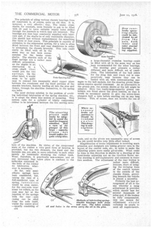
Probably the best arrangement of all is the one wherebya matia adjustment is provided --" which should last for several thousands of ' miles and, if the brakes be fully compensated, this one means for Methods of lubricating springadjustment should shackle bearings both front certainly be ample to and rear. The tubes contain
meet all requirements.