


ENGINE LUBRICATION.
Page 30
If you've noticed an error in this article please click here to report it so we can fix it.
A Résumé of Recently Published Patents.
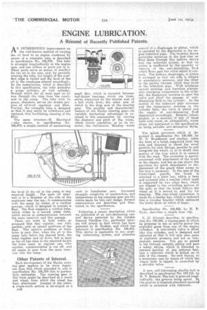
AN INTERESTING improvement on the well-known method of varying the oil level in an engine crankcase by means of a rotatable tube is described in specification No. 196,478. The tube is arranged longitudinally-in 'the -engine case, and hiss orifices, or ports cut in it. These ports serve as means of overflow for the oil in the case' and, by partially rotating the tube, the height of the overflow edge is varied and the level of the oil in the crankcase altered accordingly. In the construction, which is described In this specification, the tube embodies a gauge cylinder, or half cylinder, through which the oil must pass on its way through the tube from the erariltcase to the sump. The tube with its gauge, therefore, serves the double purpose of oil-level regulator and filter. Further, the rotatable tube is designed so that it may easily he withdrawn and replaced, thus facilitating cleaning of the filter.
The same ieventor-11. Marchand —also shows, in specification No. 196,479, a simple method of maintaining the level of the oil in the sump at any required height. The main oil reservoir is in a chamber at 'the side of the crankcase near the top ; it communicates with the sump by means of a vertical passage, which is designed to contain a float. The float supports a vertical tube, which slides in a second outer tube, which serves as communication between the main reservoir and this passage. There are holes in both tubes, so arranged that they register, one with another, only at certain positions of the float. The relative positions of these holes is such that, when the oil in the sump falls below the desired level, the holes register and oil flows, but so soon as the oil has risen to the required height the holes cease to register one with another, communication is out off, and oil ceases to pass from the main reservoir into the sump.
Other Patents of Interest. .
Each development of the Merles steering gear appears to be more ingenious than that which preceded it, and in specification No. 196,374 this is particularly noticeable. The steering gear in this form might -Ise e.scribed as a worm and wheel, from which the wheel has been eliminated. Instead of the latter, a single-tooth section is developed as a
small disc, which is mounted between ball-throat bearings, which are themselves supported on the shorter arm of a bell crank lever, the other 'arm of which is the drop arm of the steering gear. The peculiar and characteristic feature bf the Merles steering gear—its variable mechanical advantage—is retained in this construction by varying the diameter and pitch of the worm, which closely resembles, as to its exterior, the well-known Hindley worm
used in Lanchester cars. Increased strength, simplicity of construction, and compactness of the complete gear are the claims made for this new design. Several constructions are described and illustrated in the specification.
Following a recent description which we published of an anti-detonating control device patented by the London General Omnibus Co., particular interest will attach to that which has been patented by E. Dodson, and which has reference in specification No. 196,443. This device is applicable to any existing carburating system, and embodies
control of a diaphragm or piston, which is operated by the depressiriii in the engine induction pipe.' The inventor draws . particular attention to the fart that no' .fluid-flows through this bellows device into the induction system, so that its action is unaffected by the quantity or velocity of the anti-detonating fluid which flows past the valve which it, controls. The bellows, diaphragm, or piston is arranged so that one side is subject to atmospheric pressure, and the other to the partial vacuum which May exist in the induction pipe. With minimum suction existing, and therefore presumably maximum compression in the cylire der, the diaphragm operates to open the valve and allow the passage of antidetonating fluid to the cylinder. As the suction in the induction pipe increases and the compression pressure, in the cylinder falls, the valve is closed and the supply of anti-detonating fluid diminished accordingly. Benzole, toluol, alcohol, or a mixture of any of these fuels with water, or, alternatively, water alone, are mentioned la the specificatiom as being suitable anti-detonation fluids.
The splash preventer which is described in specification No. 196,408, by W. 0. Broadhurst and another, takes the form of a brush supported from the axle and disposed in about the usual position for such fittings, parallel to and alongside the wheel, so as to shield that portion of the tyre which is in contact, with the road. The invention is mainly concerned with attachment of the brush to the chassis, and has as one object the provision for quick detachment or displacement of the guard when access to the tyre is necessary. In the case of the front-wheel. guards, the brush is attached to a plain bar, which is bent and socketed into a bracket which itself is supported by two other bars, which are clipped to the swivelling portion of the axle, so. that the brush follows the wheel as it is moved to and fro for steering. The rear-wheel; connection is made by a similar bar, which is socketed into a circular bracket which embraces the brake drum on which it bears.
Specification No 196,420, by H. P. -Ryan, describes a simple hose clip.
L. G. Ginnett describes, in specification No. 196,495, a tipping gear in whisk he proposes to use as motive power the exploded gases from one of the engine cylinders. A non-return valve is fitted into this cylinder, and is designed and' adjusted so that it will only pass gases at explosion pressure and not at compression pressure. The .gas so passed is led through suitable piping and past a safety device, which is intended to prevent ignition of any unburnt fuel, into a reservoir which is bolted on to aide of the chassis. Its exit thence, to a pneumatic ram by means of which the wagon body is tipped, is controlled by a suitable valve.
A new,, self-lubricating shackle bolt is described in specification No. 194,115, by AL V. Roberts. The bolt is grooved longie tudinally, the grooves 'being spiral. In the grooves is inserted absorbent material which is saturated with lubricant.