


AIDS TO 1OLVING FORD PROBLEMS,
Page 25
If you've noticed an error in this article please click here to report it so we can fix it.
Valuable Advice on Every Phase of Ford Transport, which will Appeal to the Owner, Driver, and Repairer.
IN THIS series of hints concerning the Ford light chassis and ton truek wherever they are employed for commercial purposes, which commenced recently, we propose to deal with the subject from every viewpoint, so that the advice given will appeal to the owner, driver, maintenance engineer, or mechanic. Valuable sources of information will be tapped for this purpose, and it should be understood that the information given will all be derived from those with a practical and intimate knowledge of the subject.
We shall welcome for inclusion amongst the hints those which have proved of value to individual users, and will make suitable remuneration for any published. What we desire are the results of practice, and not so-called improvements, which are but theoretical.
48.—Tightening the Steering Wheel.
The locking nut in the centre of the steering wheel ,occasionally becomes loose. If this is the case, tighten it very carefully, as, otherwise, the nut may split.
49.—Tracing a Commutator Trouble.
One of our readers recently experienced trouble with an old-pattern Blublaze commutator. For some time the engine lost power and fired irregularly on two cylinders—always the same two. Changing the plugs and the coils inade no difference and suspicion then rested on the commutator, which was very carefully examined.
It was discovered that the bead of the retaining pin projected beyond the sleeve-edge -of the plate carrying the carbon brush, so that when the lock-nut was tightened the collar which is intended to prevent the pin from falling out caught this pin first and made the plate and its sleeve cant over, this being assisted by the fact that the sleeve was somewhat loose on its shaft.
The canting of the carbon-brush plate caused the brush to bear heavily on the two segments at one side and hardly to touch those at the other side.
A cure was effected by filing a flat at one side of the pin head so that the edge of this head came flush with the edge of the sleeve.
In conclusion, it may be useful to users of this make of commutator if we give a few hints regarding it.
It is essential that the spring behind the carbon brush should be of ample strength. If the pressure of the brush be reduced owing to its wearing shorter a wad of paper or cardboard should be inserted behind the spring. Any slight eccentricity of the brush plate may not be noticed with a new brush and strong spring, but it will probably soon make itself apparent after a little wear has taken place.
If oil persists in entering the commutator and a new felt washer does not arrest it, place some brown paper washers between the felt washer and the copper plate..
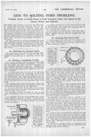
50.—Repairing Ford Stator Coils.
It often happens that where the Ford stator coils are at fault mechanics are chary of attempting a repair, as the internal economy of these coils is more or less a mystery to them.
A brief description of a stator coil should serve to remove any mystery that may surround it. Each coil is wound round one of the series of cores which form part of the stator casting and it consists of copper ribbon. This ribbon is wound into two minor coils, which are placed side by side. 'They are not separate, but nevertheless are insulated from each other, a cardboard washer being plated between them, also at both sides. Another strip of cardboard is positioned in the middle of the ribbon coils when they are joined.
The two minor coils are bound together with linen tape coated with shellac. The complete coil is then pressed on to the core of the stator casting. It is pressed hard back against the casting, and the outer side should be slightly below the face of the end of the core. If this be not done the magnet clamp faces may foul the insulation and damage it ; at the same time the clearance between the clamp faces and coreend faces would be excessive.
The complete coils when mounted should be so wound that one coil runs in the opposite direction from that to which it is joined. By this means the polarity of one core will show north and that of the succeeding core south. The ribbon end of one coil is earthed to the stator casting, whilst the end of the other, which completes the circle, is sweated to the collector block standing in the 12 o'clock position when the stator is fixed to the end of the engine block.
In winding coils, care should be taken to see that the coil to the left of the collector block is wound in a direction which would cause the core to assume a north polarity if current were passed through the coil. The whole coil assembly should be coated with shellac after adjoining coils have been sweated to one another,.
In testing an assembly which is suspected to be defective, the earth ribbon must be unsweated and brought clear of the casting.