


A NEW MECHANICAL TIPPING GEAR.
Page 10
If you've noticed an error in this article please click here to report it so we can fix it.
Devised by Maudslays for the Eagle Truck, the Apparatus is Subject to Less Strain than Usual, When Tipping.
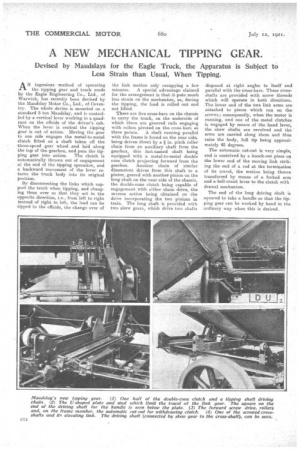
AN ingenious method of operating the tipping gear and truck made by the Eagle Engineering Co., Ltd., of Warwick, has recently been devised by the Maudslay Motor Co., Ltd., of Coventry. The whole device is mounted on a standard 5 ton Maudslay, and is controlled by a vertical lever working in a quadrant on the offside of the driver's cab. When the lever is central the tipping gear is out of action. Moving the gear to one side engages the metal-to-metal clutch fitted on a shaft taken off the .three-speed gear wheel and laid along the top of the gearbox, and puts the tipping gear into action. The clutch is automatically thrown out of engagement at the end of the tipping operation, and a backward movement of the lever returns the truck body into its original position.
By disconnecting the links which support the truck when tipping, and changing them over so that they act in the opposite direction, i.e., from left to right instead of right to left, the load can be tipped to the offside, the change over of the link motion only occupying a few minutes. A special advantage claimed for the arrangement is that it puts much less strain on the mechanism, as, during the tipping, the load is rolled out and not lifted.
There are five cross-bars on the chassis to carry the truck, on the underside of which there are grooved rails engaging with rollers pivoted on the cross-bars at three points. A shaft running parallel with the frame is found on the near side, being driven direct by a in. pitch roller chain from an auxiliary shaft from the gearbox, this last-named shaft being equipped with a metal-to-metal double cone clutch projecting forward from the gearbox. Another chain of similar dimensions drives from this shaft to a pinion, geared with another pinion on the long shaft on the near side of the chassis, the double-cone clutch being capable of engagement with either chain drive, the aeverse action being obtained on the drive incorporating the two pinions in train. The long shaft is provided with two skew gears, which drive two shafts
disposed at right angles to itself and parallel with the tross-bars. These crossshafts are provided with screw threads which will operate in both directions. The lower end of the two link arms are attached to pieces which run on the screws; consequently, when the motor is running, and one of the metal clutches is engaged by means of the hand lever, the skew shafts are revolved and the arms are carried along them and thus raise the body, full tip being approximately 45 degrees.
The automatic cut-out is very simple, and is contrived by a knock-out piece on the lower end of the moving link striking the end of a rod at the termination of its travel, the motion being thence transferred by means of a forked arm and a. bell-crank lever to the clutch with drawal mechanism.
The end of the long driving shaft is squared to take a handle so that the tipping gear can be worked by hand in the ordinary way when this is desired.