


Generating Worm Gears
Page 66
If you've noticed an error in this article please click here to report it so we can fix it.
A R6sum6 of Recently Published Patent Specifications
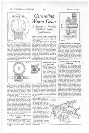
TN specification No. 362,448, the Cone 1Worm Corporation, Norfolk, Virginia, U.S.A., points out that in the cutting of worm wheels which have to mesh with worms of the enveloping type there has, hitherto, been difficulty in obtaining a correct form of tooth. This is owing to the fact that a hob of the kind required for such wheels has to he introduced in a radial direction towards the wheel, thus removing certain parts of the metal which are required to make an approximately proper mating of the wheel with its worm.
To overcome this trouble is the object of the present invention in which the wheel is first cut in •the usual manner to within a certain distance of the desired depth, by feeding a hob towards the wheel, both beine' driven in proper timed relationship by gearing. After this a second operation takes place, which, it is claimed, brings the teeth to a correct form.
A hob which has teeth thinner than that which is to work against the wheel is introduced, and is brought to the desired depth so that its axis is the exact distance from the axis of the worm wheel that the working worm will occupy, the roughing hob having cut the bottoms of the. spaces to the required depth. The wheel is then given a slight rotary movement in relation to the mechanism which ie driving it, as shown by the dotted lines, bringing first one side of the teeth in cutting contact with the hob, then the other side.
A Safety Device for Hydraulic Brakes.
SPECIFICATION_No. 361,532, by the Acme Brake Corporation, 1ASur, Zefferson Avenue. East, Detreit, U.S.A., points out the well-known fact that with ordinary hydraulic brake systems, 134.8 should a leakage occur in the duct from the pressure-generating cylinder all brakes operated by that pipe will be put Out of action.
To guard against this is the object of the present invention. A represents the cylinder in which the pressure is generated, as shown in the left view. The two pipes leading from it pass respectively to the two front and the two rear brakes. In the chamber between the two pipes is a rubber diaphragm, so formed that it acts as a valve to close either of the pipes should a leakage occur and the resistance to pressure be so relieved.
The figure on the right shows .the diaphragm acting to close the pipe on the right, preventing the escape of fluid.
An Efficient Form of Lack-nut.
THE design of lock nuts appears to have a special attractionfor inventors ; it seems strange, however, that the designers of machines seem so little inclined to adopt any of these inventions, and to depart from the spring washer and split pin.
The latest arrival is thaf described in patent No. 362,516, by A. P. Buisset, 1, Route de Prix, Mezieree, France. In this case the bolt is screwed with a thread cut in one direction where the lower of the two nuts is situated, and is reduced in diameter and screwed with a thread cut in the reverse direction where the upper nut is situated, a Grover washer being introduced between the nuts.
There is no doubt that this arrangement would form a very efficient means for locking, but the use' of two oppositely threaded nuts is by no means new, and we have known it to be used on the rear axles of chain driven vehicles. We also have an illustration of it in a technical book.
The introduction of a Grover washer would appear to be the only point of novelty, and it is doubtful whether this would be sufficient to form subject matter for a patent. • The important features in lock-nut design are simplicity and cheapness of manufacture.
Control of Electric Starters.
DESCRIBED in patent No. 362,747, by Motor Devices Corporation, 340, North Michigan Avenue, Chicago, U.S.A., is an invention the object of which is to provide a controlling means whereby a starter motor is positively and automatically brought into action before the ignition is switched on, whilst the electric circuit of the motor is automatically maintained until the engine starts, when it is broken without any manual operation.
Gear Cutting and Grinding Machines.
A SIMPLE form of gear-generating
machine, for both tutting and grinding, is shown in the patent of Edmond van Muylder, 25, Rue Louis de Coninck, Berchern-Antwerp, numbered 362,799.
The gear to he eut or ground is represented by 17, 23 being the cutter or grinding wheel. The gear to be operated upon is mounted on a spindle, to which an oscillatinw' motion is imparted by means of the flexible steel bands, drum and slide, shown. As it oscillates it passes over the cutter or grinding wheel, which may be of any desired angle, thus generating the form of an involute tooth. We presume that a sliding movement takes place as well as rocking motion, to form parallel teeth.
The crank shown imparts a rocking movement to the shaft, which causes the sliding movement of the part to which the flexible bands are attached. The rocking movement may be regulated by altering the positions of the pivots (19 and 21) should a departure from the true involute be required.