


Snap-action Pump and Nozzle Injection Unit
Page 40
If you've noticed an error in this article please click here to report it so we can fix it.
A Re'sume of Patent Specifications That Have Recently Been Published
WHILST the unit type of VT pump, t,upplying fuel t6 several cylinders, is almost universally employed on vehicle oil 'engines, its manufacture calls for the highest type of precision engineering, with propor
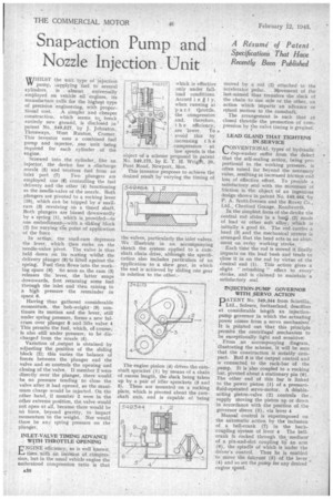
tional cost. A simpler and cheaper construction, which seems. to break entirely new ground, is disclosed in patent No. 549,527, by J. Johnston, Thrceways, West Runton, Cromer. This inventor uses' a combined fuel pump and injector, one unit being required for each cylinder of the engine.
Screwed into the cylinder, like an injector, the device has a /discharge nozzle (5) and receives fuel from an
inlet port (7) Two plungers are employed due (8) controlling the fuel
• delivery and the other (4) functioning ris the needle-valve of the nozzle. Both . plungers are pivoted to a rocking lever (10), which can be tripped by a. snailcam (3) revolving on a timed shaft. Both plungers are biased downwardly by a spring (1), which is provided—in one embodiment--.with a sliding block (2) for varying the point of application of the force
. In action, the snail-cam depresses the lever, which then rocks on the needle-valve pivot. The valve is thus held down on its seating whilst the delivery plunger (8)is lifted against the spring. Fuel then flows into, the working space (6) So soon as the cam (3) releases the lever, the latter snaps downwards, first returning some fuel through the inlet and then raising to a high pressure the remainder in space 6.
Having 'thus gathered considerable momentum, the bob-weight (9) continues its motion and the lever, still under spring pressure, forms a new fulcrum over plunger 8 and .lifts valve 4 This permits the fuel, which, of course; is also still under pressure, to be discharged from the nozzle (5).
Variation of _output is obtained by adjusting the .position of the sliding block (2); this varies the balance of forces between the plunger and the valve and so controls the opening and closing of the valve. If member 2 were directly over the plunger, there would be no pressure tending' to close the valve after it had opened, so the maximum charge would be injected. On the other hand, if member 2 were in the other extreme position, the valve would not open at all, because there would be no force, beyond gravity, to impart momentum' to the weight. Nor would there be an; spring pressure on the plunder.
INLET-VALVE TIMING ADVANCE WITH THROTTLE OPENING
ENGINE efficiency, as is well known,
• rises with an increase of cOmptession, but in the usual vehicle engine the understood compression ratio is that
54'3,527 which is effective
only under fullload conditions. Accord in gl y, when running at 'p a r.t throttle, the compression and, therefore, t h e efficiency, are lower. To • avoid this by increasing t h e
• 6 compression at low speeds is the object of a scheme proposed in patent No. '549,175, by E. T. H. Wrieft, 20; Pant Road, Newport, Mon.
This inventor proposes to achieve the desired result by varying the timing of
the valves, particularly the inlet valves. We illustrate in an aecompanying sketch the system applied to a camshaft chain drive, although the specification. also includes particulars of an application to a skew gear, inthe end is achieved by sliding oe gear in relation to the other.
The engine pinion (4) drives the cainshaft sprocket (1) by means of a chain of excess length, the slack being taken up by a pair of idler sprockets (3 and 5). These are mounted on a rocking plate, which is pivoted about the camshaft axis, and is capable of being moved by a rod (2) attached to the
accelerator pedal. Movement of the last-named thustransfers the slack of the chainto One side or the other, an action which imparts an advance or retard motion to the camshaft.
The arrangement is such that at closed throttle the promotion of corn.pression by the valve timing is greatest. •
LEAD GLAND THAT TIGHTENS IN-SERVICE
rONVENTIONAL types of hydraulic Cup-washer suffer from the defect that the self-sealing action, being. proportional to the working pressure, is often 'raised far beyond the necessary value, restilting in increased friction and loss of effective effort. To provide a satisfactory sealwith the minimum of friction is the object of an ingenious design shown In patent No, 549,464, -by P. A. Scott-Iversen and the Rover Co., Ltd., ChesfOrd Grange, Kenilworth.
In the simplest form of the devite the central rod slides in a buSjo (2)' made of lead or other soft alloy, which is initially a good fit. The rod carries a head (3) and the mechanical system is , arranged that the head acts as an abutment on ev6ry working stroke.
Each time the rod is moved it finally impacts on the lead bush and tends-to close it in on the rod by virtue of the Conical end (1). This action gives a .slight " rebushing '-' effect to everystroke, and is claimed to maintain a satisfactory seal,
INJECTION-pUMP GOVERNOR WITH SERVO ACTION
PATENT No.-549,344 from Scintilla, Ltd., Soleure, Switzerland, descfibes at considerable length an injectionpump governor in which 'the actuating power comes from a servo mechanism'. ,• It is pointed out that this principle permits the centrifugal mechanism to be exceptionally light and sensitive. , From an accompanying diagram, illustrating the scheme, it will be seen that the construction is notably compact. Rod 8 is the output control and is connected to the rack-bar of the pump. It is 'also coupled to a rocking bar, pivoted about a stationary pin (6). The other end of this bar is linked to the power piston (1) of a pressurefluid-operated servo-motor. A doubleacting piston-valve (2) controls the supply moving the piston up or down in accordance with the position of. the governor sleeve (3), via lever 4 Manual control is superimposed on the automatic action by th. inclusion of a bell-crank (7) in -the backcoupling system of lever 4 The bellcrank Is rocked through the medium' of a pin-and-slot coupling by an arm (9), the spindle of which is under the driver's control. Thus he is enabled to move the fulcrum (5) of the lever (4) and so set the pump for any desired engine speed.