


Proposed Bedford Cab
Page 82
If you've noticed an error in this article please click here to report it so we can fix it.
ilv1PROVED access to the engine for forward-control vehicles is the object of patent No. 802,178. (Vauxhall Motors. Ltd., Luton, Beds.) The drawing shows howshisis done by mounting a vertical engine at the sear of the cab under a shelf on which the driver's and passengers' seats are situated. The cab is extended ,at the rear below waistline level to allow this and doors (I), having curved cnt-aways to clear the wings, are provided at the sides of the
rear portion. • Three panels (2) forming the backrests for the seats can be hinged upwards and the seat pans (3) are also detachable to give entry to the engine compartment.
PISTON RING ASSEMBLER
PATENT No: 802,780 describes a quantity production machine for placing the rings on pistons. The pistons are presented in turn to a stack of rings on a mandrel. The machine springs each ring open and pushes it over the land into the groove_ The patent comes from General Motors Corp., Detroit, Michigan, U.S.A.
SEALING -WATER-COOLED BORES FOR INJECTORS
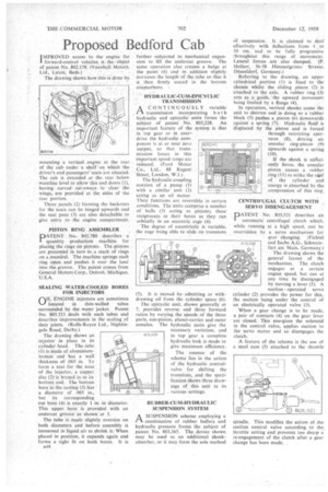
(AIL ENGINE injectors are sometimes
N.--/ located in thin-walled tubes surrounded by the water jacket. Patent No. 803,523 deals with such tubes and describes improvements in the sealing of their joints, (Rolls-Royce Ltd., Nightingale Road, Derby.) The drawing shows an
injector in place in its cylinder head. The tube (1) is made of aluminiumbronze and has a wall thickness of .065 in. To form a seat for the nose of the injector, a copper disc (2) is brazed in to its bottom end. The bottom bore in the casting (3) has a diameter of .985 in., but its corresponding top bore (4) is exactly 1 in. in diameter. This upper bore is provided with an undercut groove as shown at 5.
The tube is made slightly oversize on both diameters and before assembly is immersed in liquid air to shrink it. When placed in position, it expands again and forms a tight fit on both bores. It is
H.4# further subjected to •mechanical expansion to fill the undercut groove. • The same operation also creates a bulge at the point (6) and in addition slightly increases the length of the tube so that it
.then firmly seated in the bottom counterhore.
HYDRAULIC-CUM-EPICYCLIC TRANSMISSION .
A -CONTINUOUSLY variable intransmission incorporating bot h hydraulic and epicyclic units forms the subject of patent No. 803,228. An important feature of the systein is that in top gear or in overdrive the hydraulic component is at or near zero output, so that transmission losses in this important speed range are reduced. (Ford Motor Co., Ltd., 88 Regent Street, London, W.1.)
The hydraulic coupling consists of a pump (I) with a similar unit (2) acting as an oil motor. Their .functions are reversible in certain conditions. The units comprise a number of balls (3) acting as pistons; these reciprocate in their bores as they run orbitally in an eccentric cage (4).
The degree of eccentricity is variable, the cage being able to slide on trunnions W3,3,1-5 (5). It is moved by admitting or withdrawing oil from the cylinder space (6).
The epicyelic unit, shown' generally at 7, provides reverse arid three forward ratios by varying the speeds of the three parts, sun-pinion, planet-carrier and outer annulus. The hydraulic units give the necessary variation, and in top gear a complete hydraulic lock is made to give maximum efficiency.
The essence of the scheme lies in the action of the hydraulic control valve for shifting the trunnions, and the specification shows three drawings of this unit in its various settings.
RUBBER-CUM-HYDRAULIC SUSPENSION SYSTEM
A SUSPENSION scheme employing a rt combination of rubber buffers and hydraulic pressure forms the subject of patent No. 803,345. The device shown may be used as an additional shockabsorber, or it may form the sole method of suspension.. It. is claimed to deal effectively with deflections from 1.".to 10 cm. and to be fully progressive throughOut this range of movement. Lateral forces are also damped. (I'. Holten, 56-58 Himmelgeister Strasse, Diisseldorf, Germany.)
Referring to the drawing, an upper cylindrical portion (1) is fixed to the chassis whilst the sliding . piston (2) is attached to the axle. 'A rubber ring (3) acts as a guide, the upward movement being limited by a flange (4).
In operation, vertical shocks cause the unit to shorten and in doing so a rubber block (5) pushes a piston (6) downwards against a spring (7): Hydraulic fluidis displaced by the piston and is forced through restricting apertures (8), driving an annular ring-piston (9) Upwards against a spring (10).
If the shock is sufficiently fierce, the annular piston • causes a rubber ring (II) to strike the rsiof of the .cylinder and energy is absorbed by the compression, of this ring.
CENTRIFUGAL CLUTCH WITH SERVO DISENGAGEMENT
PATENT No. $03,521 describes an automatic centrifugal clutch which, while running at a high speed, can be overridden by a servo mechanism for gear changing. (Fichte! and Sachs A.G., Schweinfurt am Main, Germany.)
The drawing shows the general layout of the mechanism. The clutch engages at a certain engine speed, but can at any time be disengaged by moving a lever (1). A suction operated servo cylinder (2) provides the power for this, the suction being under the control of an electrically operated valve (3).
When a gear change is to be made, a pair of contacts (4) on the gear lever are closed. This energizes the solenoid in the control valve, applies suction to the servo motor and so disengages the clutch.
A feature of the scheme is the use of a snail cam (5) attached to the throttle