


A VEHICLE FOR MOTORWAYS
Page 59
Page 58
Page 60
If you've noticed an error in this article please click here to report it so we can fix it.
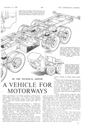
NOW that at last Great Britain can boast a motorway, albeit only 8+ miles of two-lane dual carriageway— the Preston by-pass—it is appropriate to reflect on the type of heavy goods vehicle that might be developed during the next 15 or 20 years primarily for operation upon such roads.
To make full use of motorways, as in America, maximum speeds will obviously have to be higher than today. Most present eight-wheelers, for example, can do little more than 35 m.p.h. in standard trim; at least 70 m.p.h. will be • required. The better engineering that has gone into the roads will permit higher gross and individual axle loadings and the absence of steep gradients will reduce the amount of gearwork necessary and further help to keep average ' trip speeds close to the average maximum speeds. Higher speeds will entail a complete revision of the braking systems currently used on heavy trunk vehicles, and will emphasize the importance of cab comfort, so that drivers become neither bored nor fatigued when called upon • to drive between, say, London and Glasgow in a day.
Faster Vehicles Needed
Because it will be possible to cover greater distances in a normal day's work—subject to trade union approvalmotor roads will do more than alter the design of vehicles. The higher speeds will materially affect running schedules and procedures, and could result in a reduced number of vehicles being employed on long-distance services. This depends upon the rate of swing of the traffic between the railways and the roads. It also depends upon reduced terminal delays, and good access roads into the centre of industrial areas and docks are essential.
Although in America, where such roads are common. the articulated outfit is the favourite for long-distance haulage, it does not necessarily follow that the use of this type will continue to grow in popularity in this country. Subject to terminal delays being reduced, an eight-wheeler running at 28 tons gross and possibly towing a drawbar trailer running at 14 tons gross should be a practical proposition for the long-distance operator, giving greater payload capacity in terms of size and weight than a normal articulated outfit could afford.
A 28-ton-gross eight-wheeler should be able to carry 21-22 tons on its back, whilst a further 11 tons could be loaded on to the trailer, giving a payload of well over 30 tons all told.
70 m.p.h. with an Eight-wheeler
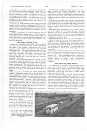
An eight-wheeler capable of at least 70 m.p.h. would retjuire an engine of not less than 300 b.h.p. Possibly more important than the maximum output, however, will be the maximum governed engine speed, which, ideally, should not be lower than 3,500 r.p.m. In this way not only is a favourable maximum speed assured, but the wide enginespeed range will help to give good acceleration without the need for more than five gear ratios. A torque output no lower than 650 lb.-ft. at about 1,500 r.p.m. is envisaged as being necessary for good acceleration, and for hill-climbing when off the motorways.
It is not likely that either gas-turbine or free-piston engines will be sufficiently developed for this class of work within the period under consideration. Therefore, unless petrol injection can give oil-engine economy from a lighter, cheaper and more compact petrol engine, the trunk vehicle of the future will continue to rely upon an oil engine for its power.
To reduce the size of the unit, a high-speed V-8 twostroke of about 7 litres is envisaged, an output of 300 b.h.p.
being well within its capabilities. To save 'weight and eliminate cooling troubles, I would suggest that the unit be air cooled, employing a thermostatically controlled fan. B24 Noise could be deadened by adequate cab insulation, which would not be difficult to apply, as the engine would lie beneath the cab.
Because a semi-automatic gearbox is contemplated, a manually operated clutch is ruled out. To give maximum fuel economy when running at normal speed, a coupling similar to the Self-Changing Gears Fluid-Friction unit should be satisfactory. This would give a smooth take-up of drive through the hydraulic coupling when accelerating, with a positive drive through the friction clutch at above 1,000 engine r.p.m.
Foom this coupling the drive would be taken by a rubberjointed propeller shaft to a five-speed semi-automatic hydraulically actuated gearbox, with overdrive top gear. With a standard axle ratio of 6 to I, direct drive would give a maximum speed of 70 m.p.h., whilst the overdrive ratio would increase the potential maximum to well over 80 m.p.h., but, more important, would allow the vehicle to be cruised at 70 m.p.h. at lower engine speed, with subse7. quent benefits in fuel economy and reduced wear and noise.
It would be sufficient for bottom gear to be no lower than about 6 to 1. as this would give a theoretical gradien!
ability approaching I in 4 when operating at 28 tons gross solo weight, and at least '1 in 7 with a 14-ton drawbar trailer.This performance would be more than adequate for working over normal British roads other than the motorways.
Gear changing would be controlled by a "finger-tip" lever mounted close to the steering wheel. A worth-while adjunct to the gearbox would be a hill-holder device similar to that offered by Leyland Motors. Ltd., in their PneumoCyclic version of the Self-Changing Gears semi-automatic epicyclic gearbox. This would eliminate the chance of accidents occurring on steep gradients through vehicles running backwards in the event of brake failure.
Behind the gearbox some form of hydraulic retarder, actuated by a separate control in the cab, would be fitted. This would act as an initial brake to avoid the use of the wheel brakes when descending a steepish gradient or when merely wishing to reduce speed gradually.
Unlike most braking systems, however, the energy built up in the retarder need not be wasted to atmosphere in the form of heat, but, because an all-hydraulic power system is envisaged, the output from the retarder could be fed into the hydraulic accumulators to supplement the supply from the normal engine-driven pump.
Using rubber-jointed propeller shafts again, the drive would be transmitted from this remotely mounted gearbox to the double-drive rear bogie. Because of the high torque that will have to be absorbed by the axles. I am in favour of using overhead-worm-drive units. The present shortcomings of worm axles for high-speed work can be overcome by a thrust-pad layout for the worm wheel, such as has been recently developed by Leyland Motors, Ltd. The use of worm axles in a double-drive bogie is also simpler and less eipensive than an arrangement employing spiral-bevel axles.
No third differential would be fitted. The main reason for using one is to reduce tyre wear, but this is a theoretical advantage and when running over icy or greasy roads a third differential can be a disadvantage. In the interests of safety, therefore, there is no need for such a device for motorway working, but a limited-slip third differential, as offered by Guy Motors, Ltd.. could be fitted. Although there 4s much to be said in favour of air suspension for any type of goods or passenger vehicle, there are many instances where a good rubber system can give perfectly satisfactory results. As standard, therefore. I would suggest that the suspension medium at the front and rear bogies should be rubber. The bogies could be of the walking-beam type, along the lines of the American Hendrickson bogie, as manufactured in this country by-the Eaton Axle Co., Ltd.
The layout of the Hendrickson bogie affords more than sufficient articulation for normal purposes, whilst the rubber "load cushions," which form the suspension medium, give a good,ride under varying conditions of load, do not require lubrication, and simplify installation as compared with air suspension.
A further consideration in favour of rubber is that the vehicle will have only hydraulic power. To use air suspension would necessitate a second power system, unless, of course, some form of hydraulic-pneumatic suspension, such as is used on current'Citroen DS19 and ID19 private cars, were to be employed.
Disc Brakes: Anti-skid Device Braking on a high-speed vehicle of this weight is of prime importance, but fortunately we are already approaching the answer to this problem. High-capacity disc brakes suitable for the weights envisaged are well into the development stage. Disc brakes would, therefore, be fitted to all four axles, with single-caliper units for the front wheels and twin-caliper rear brakes. Twoseparate disc units behind each rear axle would be actuated with hydraulic assistance by a single-pull lever with a pull-up action from floor level.
Because of the disastrous results of a vehicle of even 28 tons gross weight (let alone 42 tons gross) locking its wheels at anything over 60 m.p.h., some form of anti-skid device is imperative. The most suitable so far available is the Dunlop Maxaret unit, which can be used only on a hydraulic system in which there is a continuous flow of fluid, such as would be easy to provide on this hypothetical vehicle.
The power valve controlling the brakes would work through a dual-circuit system and to guard against the failure of hydraulic pressure the valve could incorporate a conventional master cylinder, so that the driver could exert manual effort on the brakes. To afford maximum comfort under such conditions, a " two-foot " brake pedal could be employed, with a large pad on each side of the steering column. Not only would this give the driver, a chance to apply both feet in an emergency, and hence extra pressure, but it would cater for drivers who preferred to brake with their left feet instead of their right.
Steering will also have to receive careful consideration and the greatest efficiency is usually given by a recirculatory-ball gear. A compact hydraulic power ram acting directly on the steering drop arm would be equipped with a cut-out control so that sensitivity was not lost on slippery road surfaces.
A short steering column is.contemplated, so that the steering wheel lies in a horizontal plane on a level little above that Of the driver's seat cushion. This would give comfortable driving.
I do not envisage anything revolutionary in chassis-frame design—certainly not integral construction. The frame should be as simple as possible, with an overall width conforming to whatever internationally accepted standard might be current at that time. The frame would be flat topped throughout its length, with bolted assembly for extra strength.
In laying out the chassis frame, thought should be given to pallet-type platform bodywork, being used experimentally by British Road Services, in which three quickly detachable pallets form the body of an eight-wheeler. This system, if generally adopted, could do much to reduce turn-round delays.
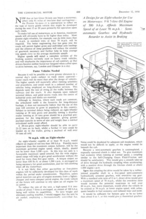
Unit accessibility is-as important as cab comfort, particularly as the engine will be beneath the seats. For this reason the cab will be arranged to tilt forward, pivoting about a point at the front of the chassis and counterbalanced—mechanically or hydraulically—to reduce the manual effort required to tilt it.
Although ease of entry to the cab is not as important on a vehicle of this type as it is on a 3-5-tonner likely to be employed on local delivery work, it is considered to be a selling point, and a tilting cab lends itself to the provision of an entrance step ahead of the front wheels to dispense with the need for a hub step ring. The cab would be as short as possible to provide extra body length within the legal limits.
Because the cab floor will lie above the frame line, the seat line will be high, thus giving the driver better vision than is possible with some layouts where the seats are relatively low. The cab framing will include a robust front bumper, integral with which will be the' cab-tilting pivot brackets. From the bumper robust channel-section members continue rearwards to form the cab base framework.
Safety Straps and Rubber Padding
The seats would be attached to this framework and lap straps would be fitted. Strain on the straps in the event of an accident would be taken by the cab sub-frame, which would tend to reduce injury to driver or passengers. The cab interior ahead of the seats could be rubber padded further to reduce this risk.
The upper structilre of the cab would consist of moulded plastics panels based on a light-metal framework. A wide field of vision would be provided by a deep curved one-piece windscreen with glazed panels beneath it to give a closerange forward vision, and wide curved rear quarter lights. The driving slat would be separate from the twoor threeman passenger seat and would be fully adjustable. Creature comforts would be catered for by fitting fresh-air heaters and a wireless set. Dual headlamps and flashing direction indicators at front, rea'r and side would be fitted.