


Patents Completed.
Page 24
If you've noticed an error in this article please click here to report it so we can fix it.
Improving Bearings.
F. R. Putz, No. 18,789, dated 16th August, 1912.—This invention relates to white-metal bearings in which the white metal is held in place in the shell of the bearing by skeleton frames. Difficulty is experienced with this construction, for the shaft wears down on the skeleton as the white metal wears away, and so gets badly scored. Another difficulty is that the screw or rivet which holds the skeleton in place generally projects above it and damages the shaft badly if the white metal runs out. These two difficulties are overcome by counter-sinking the hole for the locking stud so that its head lies well below the rest of the skeleton frame; to meet the other difficulty, blocks of brass or gunmetal are embedded in the white metal some distance below its surface but. above the surface of the skeleton frame. Thesek blocks take the actual shaft contact, and provide a bearing which does not damage it in the event of the white metal's wearing or melting out.
A Wolseley Carburetter.
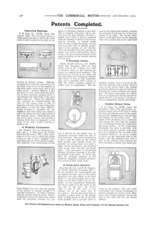
The Wale*ley Tool and Motorcar Co., Ltd., and A. A. Remington, No, 24,316, .dated 2nd November, 1911.—This carburetter is of the type in which the engine suction is used to lift a weighted valve controlling the air intake and fuel supply. The difficulty with carburetters of this
kind hitherto has been that the quality of the mixture is constant, though it is variable in quantity. In order to arrange that the mixture shall be richer, when it is desired to obtain the full power, rather than the maximum economy for any speed, an additional chamber is provided. This is supplied with petrol fed by gravity from the float chamber through a needle valve which is directly operated from the throttle, as shown in the accorn-,panying drawing. A tapered needle valve is used, so that the supply of extra fuel from this valve is directly proportional to the opening of the throttle. When the throttle is not fully opened, the engine runs with a weak mixture, that is to say, with an economical mixture at the speed depending on the throttle opening and the load.
A Parcelcar Clutch.
Marks (Tenet and „Co.), No. 28,275, dated 15th December, 1911.—A loose pulley such as the V-pulley for a belt is mounted freely on ball bearings between two conical clutch members. The left hand one is fixed on the shaft, and the right hand one—forming an ordinary cone clutch—is free to slide longitudinally, and is provided with a spring to had the clutch members pressed together when in engagement. The con trol is effected by the double cam arrangement mounted within the hub of the mechanism. One cam is mounted on a sleeve and the other on the central fixed spindle, and suitable means are provided for giving these two cams a slight relative movement ; one therefore rides up the other and they are forced apart. This movement is transmitted through ball-thrust bearings to the sliding member of the clutch. It will be seen that the principal members of this clutch are completely enclosed and therefore protected from rough usage.
A Chain-drive Gearbox.
Hans Renold, Ltd.. and D. R. Simpson, No. 24,597, dated 6th November, 1911.— In this gearbox two countershafts and two chains are. used, each of the chains travelling over gear wheels on all three shafts, i.e., the driving shaft and two layshafts, or the driven shaft and two layshafts. In the construction illustrated, the driving shaft is in the centre at the top side of the box ; the driven shaft is also in line with it and extends out. of the other side ef the gearbox. For the first chain there is provided a pinion loose on the driving shaft, another pinion is fast on the lefthand layshaft, and a sprocket wheel is loose on the right-hand layshaft ; clutches are arranged to lock any one of the loose wheels to its shaft. The second chain, shown in dot-dash lines on the diagram, runs over a pinion fast on the right-hand layshaft ; another pinion is loose on the left-hand layshaft, and a larger wheel is loose on the driven shaft.; the various speeds are obtained as may be desired by bringing the various clutches into operation. Provision is also made for a direct drive by coupling the driving and driven shafts direct to one another, and the reverse is obtaijsed by outside gearwheels.
Another Rotary Valve.
A. G. Clark, No. 24,808, dated 7th November, 1911.—This specification describes a rotary valve of the type in which the inlet and exhaust ports of the engine are put into communication with the inlet and exhaust by the rotary valve. The Object of the invention is so to construct and arrange the valve that the pressure on it is balanced during the compression and firing strokes. In the construction illustrated, the valve is provided with four ports, and the cylinder ports enter the valve chamber at the two ends of the horizontal diameter. A suction conduit is shown on the right-hand side of the engine, and this communicates with a port in the cylinder head entering the valve chamber, a similar port being pro vided kr the exhaust. The valve itself is provided with internal diaphragms to provide passages for cooling water, there being four of these passages around the edge of the valve and also one central passage.