


Patents Completed.
Page 28
If you've noticed an error in this article please click here to report it so we can fix it.
SUSPENSION OF VEHICLES.—De ostalot and Another.—No. 18,716, dated, nder Convention, 22nd August, 1906.— 'he frame (S) of the vehicle carries a cyinder (C) in which a piston CP) is conected to the wheel hub (E). Between he end of the cylinder and the piston, a ushion of compressed air or gas, suffilent to balance the load, is enclosed. he cylinder communicates by a conduit Cl) with a reservoir (R) of any suitable ize, but adjustable, as to volume, either ■ y displacing a movable wall, or by in. reducing liquid. In order to avoid the nodifications which would be necessary n frames and bodies, a system of levers, hown in Figure 2, may be employed. In his figure it will be seen that the hub caries a vertical arm (M), the upper end )f which serves as a pivot (0) for the 10 degrees lever system (A, 0, (3). One snd (A) of this lever system is connected, 3y means of a rod (B), to the piston (P), which moves in the cylinder (II). It will 3e seen that this arrangement allows the lever system to convert the vertical movements of the frame, wheels, and hub, into iorizontal movements of the rod (B), and, :onsequently, the piston (P).
SWITCH.—Kelly.—No. 25,429, dated 12th November, 1906.—The socket (Ni) of he high-tension cable (G) is connected to :he plug (E) by the terminal (k). The socket (Ni) has an extension (M1), and this has a switch-blade (B1) pivoted to it at Fl. The blade (81) has an insulated handle at one end (H1). It will be seen that, by advancing the blade (B1), which is electrically connected to the high-tension cable (G), towards the earth portion (E) of the plug, a means for testing the sparking, and earthing the cable, is obtained. The continuity of the circuit may be ciete7mined by bringing the switch-blade (B1) to within a short distance of the plug (El, and observing, while the engine is running, whether or not a spark jumps this short gap.
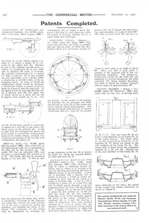
RESILIENT WHEEL. —Ibbetson. — No. 7,855, dated 4th April, 1907.—The wheel has two rims, an inner, or spoked, rim (A), and an outer, or tired, rim (B) ; between these, four laminated springs (C) are placed. In the centres of the springs (C) brackets (D) are arranged and these are secured by bolts (E) to the centre rim (A) to prevent lateral displacement. The springs are made with eyes (G) to receive connecting links (F) ; lugs (H) are riveted
to the underside of the rim (B) to receive the links (F), which are secured thereto by bolts and nuts (K, j).
RETAINING DEVICES FOR LEVERS.—Ashton.—No. 1,516, dated 21st January, 1907.—This invention relates to catch or retaining devices for levers, and its object is to provide a device for checking and holding the lever at different points of its movement. A lever (A) is provided with a bracket (Al) in which is formed a notch or recess (B). Formed in each side of the notch is a brake or shoulder (B3). A pin (C, C1) is carried by a plate (C2) on a rod (C3), the end of which passes through a lug (A2 projecting from the lever over the bracket (Al). A spring (C4) on the rod (C3) tends to press the end portion (C) of the pin into the notch (B), the pin, however, being free to be forced upwardly against the action of the spring. Formed in a quadrant (DI is a slot (D1) having a series of projections (D2), each situated opposite to a notch or recess (D3), the number of these projections corresponding to the number of positions in which the lever (A) is desired to be moved. The pro jections (D2) are V-shaped, the sides forming, approximately, an angle of about 600. The sides of each notch (Di) are also in clined to each other at an angle of about 60'. Thus, one side oi each notch in parallel to the opposite side of the corresponding projection. The spring-controlled pin carried by the lever has one extremity (C) formed hexagonal, the other extremity (C1) being fanned five-sided, two sides of which are formed V-shaped with an angle of, approximately, 600.
ENGINE FRAMES. — Royce. — No. 27,860, dated 7th December, 1906.—The crank case (A) has four projecting arms (19, B, C, C). The rear arms (B, B) are fixed to side members of the frame (D, D) in the usual manner. The front arms (C, C) are connected by levers (G, G) to brackets (E, F) which are bolted to the side members of the frame (D, D). The lower ends of these levers are connected together by a tie rod (H). Should one of the side members of the frame (D, D1 move relatively to the other, the centre of the cranks will remain stationary, as shown in Figure 3.