


Why Wheel Alignment Demands Extreme Accuracy
Page 35
Page 36
If you've noticed an error in this article please click here to report it so we can fix it.
We Explain How Slight Toe-in or Toe-out of the Front Wheels Causes Transverse Sliding which, in Turn, Greatly Acceler ates Tyre Wear
rONSIDERABLE interest has been '-'evoked by a statement made by our contributor, " L.V.B.," in an article entitled " Check Wheel Alignment and Save on the Tyre Bill," which appeared in our issue dated July 29. He pointed out that, if the front wheels of a vehicle were permitted to run with a toe-in of * in., the effect was to skid one of the tyres broadside for about 11 yds. every mile.
This• enlightening statement has, apparently, been received with some incredulity. Accordingly, we are showing how transverse sliding may, indeed, assume remarkable proportions when even slight misalignment exists.
The degree of side slip for a given linear measurement of toe-in or toeout is, of course, directly dependent upon wheel diameter, because the longer the radius the smaller the angle. Moreover, it is necessary to be quite clear as to exactly how the amount of toe-in is measured. In quoting 11 yds per mile, " gave no figures for the tyre size, nor did he precisely explain how his
was arrived at. We are, therefore, taking a specific case, regarding the wheel and tyre as a disc, assuming it to have a 15-in, radius and measur
ing the toe-in as the difference between the respective distances separating the foremost and rearmost points of the near-side and off-side discs.
This difference we are taking as I in., so that, when the near-side front wheel is parallel with the rear wheels, the off-side front wheel is at such an angle to it that the distance from the front of one to the front of the other is -lig in. greater than that from centre to centre and * in. greater than that from the rear of one to the rear of the other.
Geometry of Misalignment.
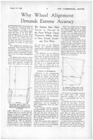
Reference to the accompanying diagram, on which the wheels are indicated by ellipses, will elucidate the above and will enable the subsequent reasoning to be followed. .In the drawing, the rectangle DEGH is defined by the two foremost points of the wheels when they are correctly aligned and the two centres. As we are assuming the wheels to have no splay in a vertical sense, there is no diffdrence between the measurement along the axle or along the ground between the points of contact, whilst to take king-pins into consideration only confuses the issue.
The simplest method of studying a problem such as this is the easiest to comprehend, and the ignoring of these complications does not affect the solution.
This rectangle DEGH represents the ideal position when the vehicle is travelling at, say, 20 m.p.h., and, in this case, the tyres will have been correctly tracked when stationary, so that, after splaying outwards due to the forward movement, they are exactly parallel.
Now, let us assume that, instead of being * in. toed-in when stationary, they are parallel, that is, are actually in. out of correct setting.
When the vehicle moves forwards the tyres will splay out 1 in. Their new relative positions are indicated by figure DFGH. This is the actual position when travelling forwards if the tyres have been set parallel 'when the vehicle was stationary. The distance EF, therefore, is Tig in.
As stated earlier, the radius of the tyres is 15 ins. The point A is the position the part G will assume at the end of one mile, that is AG = 1 mile = 63,360 ins. Similarly, BE will be 63,360 ins., but the tyre point E will not have reached B at the end of the mile; it will be at C. Therefore, the distance BC represents the side skid which is to be calculated.
By the theory of similar triangles, BC BE = EF ÷ EH. Accordingly, BC ÷ 63,360 = -rig -.15. Thus, BC = approximately 264 ins., or 22 ft.
In arriving at 11 yds„ or 33 ft. per mile for the side drag, " L.V.B." probably assumed a larger wheel diameter, and may have measured his toe-in as the difference between front distance and centre distance.
In the above calculation, it may be noted that we have regarded the lines AC, DF and GH as parallel. Actually, these lines would not be quite parallel, but the degree of error is not so slight as to be negligible.
A more accurate representation is afforded by the other diagram. In this, points G and H are, as before, the wheel centres, whilst D and F are the foremost points of the tyres when the vehicle is moving, that is, toedout in. Clearly, DF is not parallel to GH.
In the same manner, assuming the vehicle travels forwards from Cal for exactly one mile, G will be at A, but the off-side tyre will travel over to the right for one mile and H will be at C. AG and CH are, therefore, both one mile. In the solution of this problem, the track dimension GH is needed; therefore, we are taking an average figure of 54 ins. Thus DF = 54* ins. What we need to discover is the length of AC-64 ins.
It is not proposed to include the working involved in the solution of this problem. By trigonometry it can be ascertained, from the data available, that AC = 357 ins. Accordingly, AC — 54 ins. measures 25.3 ft.
This discrepancy of 3.3 ft. reveals two matters. It shows that, in calcu
lations of this description, when the distance travelled is large in relation to the wheel diameter and it is necessary in the reckoning to multiply by large figures, accuracy is of great importance. It also emphasizes the need for similar precision in making the actual adjustments.
Whilst attributable to a different cause, but, nevertheless, appropriate to the foregoing, another source of tyre wear is more common than is generally thought. This is a slight variation in wheelbase on the two sides of the vehicle.
We are informed by the service manager of a tyre company that, of 100 vehicles which were measured for this form of misalignment, no less than 29 had a variation of more than in. in the hub cap distances on the two sides.
Checking this dimension is not easy, unless an accurate pair of trammel gauges be available, and these, unfortunately, are even more rarely found in an operator's equipment than good alignment' gauges.
The usual causes of this fault include a bent front or rear axle, a broken dowel pin in a spring allowing the axle to move slightly, a broken leaf, or the loss of initial set in a spring. In the last-named case, the fast that one spring has sagged causes the shackle to move either forwards or backwards, according to whether the spring is located in front of or behind the axle beam. As the. shackle moves, so the axle on that side will be displaced in the same direction for half the distance.
Most people are amazed when this state of affairs is proved to them by means of correct gauges, never dreaming that their axles get out of parallel. Attention to details such as this, however, and to correct frontwheel tracking, is repaid by materially bigger tyre mileages.