


FORD CONVERSION SETS.
Page 24
If you've noticed an error in this article please click here to report it so we can fix it.
A Résumé of Recently Published Patent Specifications. •
There are two patents this week concerning fitting for converting Ford or other touring-ear chassis into commercial vehicles with a capacity of a ton or thereabouts. Both are of a type in which a supplementary frame is secured to the existing chassis.
One of them is specification No. .128,858. This patentee makes the , brackets for the forward ends of the semielliptic rear springs do duty also as sup
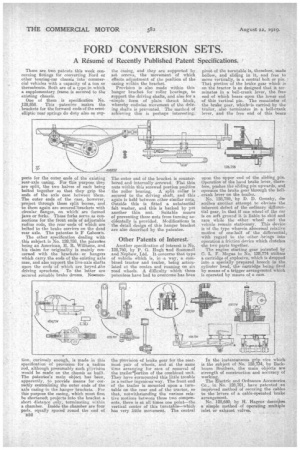
ports for the outer ends of the existing rear-axle casing. For this purpose they are split, the two halves of each being bolted together so that they grip the ends of the axle case between them. The outer ends of the case, however, project through these split bosses, and to them again are secured=hrackets with circular flanges, on which are 'formed jaws or forks. These forks serve as connections for the front ends of adjustable radius rods, the rear ends of which are bolted to the brake carriers on the dead rear axle. The patentee is F Osbourn.
The other specification dealing with this subject is No, 128,758, the patentee being an American, II. B. Williams, and his claim for Originality is mainly concerned with the brackets or hangers which carry the ends of the existing axle case, and also support the live-axle shafts upon the ends of which are keyed.ithe driving sprockets. To the latter are secured suitable brake drums. Noisanen tion, curiously enough, is made this specification of provision for a radius
rod, although presumably such !vision would be made on the chassis as built. The patentee's main object has been, apparently, to provide means for correctly centralizing the outer ends of the axle casing in the hanger brackets. For this purpose the casing, which must first be shortened., projects into the bracket a short distaiace only, terminating within a chamber. Inside the chamber are four pads, equally spaced round the end of
B52 the casing, and they are supported by set screws, the movement of which effects adjustment of the position of the casing within the bracket.
Provision is also made within this hanger bracket for roller bearings, to support the driving shafts, and also for a –simple form of plain thrust block, whereby endwise movement of the driving shafts is prevented. The method of achieving this is perhaps interesting.
The outer end of the bracket is counterbored and internally screwed.'Tint thin nuts within this screwed portion position ' the roller bearing. A split collar is secured to the driving shaft, and this again is held between other similar nuts. Outside this is fitted a substantial felt washer, and this is hacked by yet another thin nut. Suitable means of preventing these nuts from turning accidentally is provided. Modifications in the detail design of this hanger bracket are also described by the patentee.
Other Patents of Interest.
Another specification of interest is No. 128,760, by P. G. Hugh 'and Scarnmeli arixi Nephew, Ltd. It concerns that type of vehicle which is, in a way, a combined tractor and trailer, being articulated at the centre and running on six road wheels. A difficulty which these patentees have had to overcome has bran the provision of brake gear for the rearmost pair of wheels, and at the same time arranging for ease of removal of the traileiliortion of the combined unit. They have surmounted this little trouble in a rather ingenious' way. The front end of the trailer is mounted upon a turntable on the rear end of the tractor, so that, notwithstanding the various relative motions between these two components, there is at all times one point—the vertical centre of this turntable—which has very little movement. The central pivot of the turntable is, therefore, Made hollow, and sliding in it, and free to move vertically, is a central bolt or pin.: That portion of the brake gear which is on the tractor is so designed that it terminates in a bell-crank lever, the free end of which bears 'upon the lower end of this vertical pin. The remainder of the brake gear, which is carried by the trailer, also terininates in a bell-crank lever, and the free end of this bears upon the upper end of the sliding pin. Operation of the hand brake lever, therefore, pushes the sliding pin upwards, and operates the brake gear through the bellcrank lever on the trailer.
No. 128,759, by D. D. Ormsby, describes another attempt to obviate the inherent defect of the ordinary differential gear, in that if one wheel of the car is on soft ground it is liable to skid and race while the other wheel and the • vehicle remain stationary. This device is of the type wherein abnormal relative motion • of one-half of the differential., with regard to the other -brings into operation a friction device which clutches the two parts together. The engine starting gear patented by C. L. F. 'ague in No. 128,774 utilizes a cartridge of explosive, which is dropped into a specially prepared breech in the cylinder head, the cartridge being fired by means of a trigger arrangemznt which is operated by means of _a cam.
In the -instantaneous grip vice which is the subject of No. 128,734, by Backhouse. Brothers, the main objects are strength of construction and accuracy of working.
The Electric and Ordnance Accessories Co., in No. 128,701, have patented an improved method of securing the cables to 'the levers of a cable-operated brake arrangement. No. 128,680, by H. Hagens 'describes a simple method of operating multiple inlet or exhaust valves.