


Air brakes, 11
Page 39
If you've noticed an error in this article please click here to report it so we can fix it.
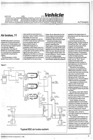
-IAVING discussed in previous irticles the components which nake up an air brake system we an now look at a typical system n its entirety. Figure 1 eproduced by courtesy of 3endix Ltd, illustrates a system or a truck which is designed to neet the EEC directives on raking.
The compressor on this system has a built-in unloader valve which is controlled by a governor valve. A safety valve is also fitted. Air from the compressor passesth rough an air drier to two service reservoirs and one parking reservoir. Each is fed through an individual single circuit protection valve fitted close to it. These valves ensure that should one portion of the system fail the feed to the other parts not affected by the failure continues to operate to enable the vehicle to be stopped with the efficiency prescribed for the secondary brake. As an alternative to the three single-circuit protection valves a single multi-circuit protection valve could be used.
A dual foot-brake valve controls the service brake system operating the diaphragms of the spring brake actuators; one side of the valve applies the front brake and the other the rear. Should one half of the system fail the other will remain effective. The air supply to the rear brakes passes through a variable load sensing valve which varies the pressure applied to the diaphragms in accordance with the load carried by the axle.
The hand control valve controls the secondary and parking brakes. As the handle is • moved from the "Off" position towards the Secondary/Park position, air is gradually exhausted from the spring brake actuators which allows the brake spring to extend. Progressive secondary braking is provided by the increasing spring pressure on the service brake push rod. At "Park" the air pressure has been fully exhausted and the vehicle is held stationary by the force of the spring brake alone.
The service and parking circuits are connected by two differential protection valves, one for the front and one for the rear axle, to prevent both systems being in operation at the same time. If this was allowed to occur the foundation brake would be overloaded.
Low pressure indicators are fitted to each of the three reservoirs and although pressure gauges are not shown in the diagram these would also be fitted.
An ordinary stop light switch is fitted in the line coming from the foot valve and another as the pressure falls, is provided for the spring brake circuit.
Quick release valves are installed adjacent to the brake actuators to hasten the exhaust of air from the actuators when the pressure is released. If they were not used the air would have to travel back to exhaust at the brake valve, which is normally located some distance from the brake.
The system described is one of several options available to meet specific requirements. A tractive unit for an artic or rigid drawbar trailer, for example, will require an additional reservoir and other additional equipment for the trailer.