


Lorry Attachment for Snow Ploughing
Page 36
If you've noticed an error in this article please click here to report it so we can fix it.
WHILE daily shade VV temperatures are keeping up to those standards -commonly associated with an English summer, it seems incorrect to describe snow-clearance as a topical matter. Nevertheless, the time is at hand when highway authorities should give thought to providing equipment for efficient accomplishment of the vital work that is not far ahead. Topical interest, therefore, does reside in an attachment which enables a lorry to function as a snow plough and which forms the subject of patent No. 546,433 from W. fiance, Ivy Cottage, Ashbury, Swindon.
Chief feature of the design is the use of a swivelling snow-blade. By this ,device the plough is rendered capable of impelling snow to either side of the road.
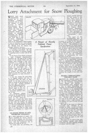
To the front of the vehicle is secured a rigid U-shaped channel-section extension (3), the legs of the U being fitted to the chassis frame and the angular bend forming a nose which terminates in a point at the front. Here is pivoted centrally the, kingpin (1) of the swivelling bar which carries the snow-blade (2). The included angle of the point is 100 degrees. This permits the plough to be inclined, on either side, at 50 degrees to the line of travel, whilst a solid abutment in both directions is provided.
A stay (4) retains the snow-blade in its angular position and may be transposed from the right, as illustrated, to the left, so as to set the blade to sweep to the of Instead of to the near side. Further provision is made for adjustably anchoring the blade to afford the desired angle to the vertical, and for holding it in a horizontal position when out of use.
An additional scheme covered by the specification is the construction of the blade in two parts—an upper and a lower—the latter being normally retained in plane •(or rather in arc) with the former, by spring loading, and being capable of yielding in a rearward direction in the event of the plough striking an obstruction, such as a large stone or other body likely too damage to a rigidly fixed element.
OIL-ENGINE PISTON TO GIVE VOLUMETRIC EFFICIENCY I N a small high-speed oil engine, the space available for valves, injector and sir-cell is limited, and this means that the jets of fuel have to be unduly short, with the consequent risk of wetting the walls of the cell.
To avoid this, by providing the longest possible path for the fuel spray,. is the main object of an improved piston shown in patent No. 546,500 by specialists in the subject, L. Gardner and Sons, Ltd., and others, Barton Hall Engine Works, Patricroft, Manchester. Another aim_ is to cause the final movement of the air to take place in a " downstream " direction.
The upper of the accompanying pair of drawings relating to this 'invention is a plan of the proposed head, whilst the lower is a section on the line A-A. The, positions of the valves are indicated by dotted circles. The injector (2) produces three jets of fuel, as shown, spaced apart by angles of 60 degrees. The large flat area (1) of the piston is instrumental in causing, at top,dead centre, a powerful transierence of air into the combustion chamber in substantially the same direction as the fuel.
This feature, it is stated, enables the air-swirl to 'be appreciably reduced, with a corresponding ,increase volumetric efficiency and power output.
It will be observed that the combustion chamber is not symmetrical in shape, when viewed in plan, but has more curvature on one side than on the other. This scheme, combined with a recessed positioning of the injector, equalizes the lengths of 'the three fuel jets. READILY DISMANTLEABLE PORTABLE CRANE
PATENT No. 546,506 comes from that well-known American concern, R. G. Le Tourneau Incorporated, Peoria. Illinois, and describes a tractor-operated crane, designed with a view to quick dismantling and assembly, for convenience of transport.
We illustrate in an accompanying sketch, the crane ready for use, the tractor being shown in dotted lines. The base is a triangular structure (6) equipped with a towing attachment at the front and a wheeled axle at the rear. Pivoted about the axle are the ends of the main legs (5). These are made to form a rigid assembly by the addition of a`pair of struts (3) and a spacer (4).
The head of the crane is a separate removable unit, attached to the • uprights by bolts. A pair of sheaves (1 and 2) carry the lifting cable, which is hauled by one part of a two-drum power-take-off on the • tractor. The second part is used to operate the luffing cable which traverses sheave 1, descends to an anchor sheave (7) and is then taken up again to the head where it is fixed.
The crane can be used in any position between upright and almost horizontal, the load capacity varying; of course, with the angle.