


Sound Ideas in U.S.A.
Page 32
Page 33
If you've noticed an error in this article please click here to report it so we can fix it.
Producer-gas Plant
IFgas-producer engineers are to be allowed, or (better) encouraged, to continue. doing•research, considerable interest attaches, to a design originating from America. If not, there is little point in our drawing attention to it. We act on an Optimistic assumption.
The design relates to a complete vehicle plant for the consumption as fuel of ' solid combustible," and it constitutes an embodiment of several ideas that are not without novelty and, certainly, interest.
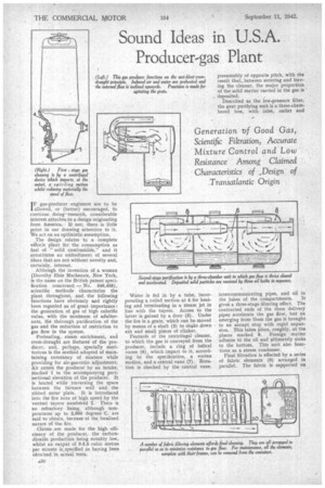
Although the invention of a woman (Dorothy Elsie Mackenzie, New York, is the name on the British patent specification concerned No. 545,458), scientific methods characterize the plant throughout, and the following functions have obviously and rightly been regarded as of great importance: the generation of gas of high calorific value, with the minimum of adulterants, the thorough purification of the gas and the reduction of restriction to gas flow in the system. Preheating, steam enrichment, and crods-draught are features of the producer, • and, perhaps, specially meritorious is the method adopted of maintaining constancy of mixture while providing for air-gas-ratio adjustment. Air enters the producer by an intake, marked 1 in the accompanying part. sectional elevation of the producer. It is heated while traversing the space between the furnace wall and the ribbed outer plate. It is introduced into the fire zone at high speed by the venturi tuyere numbered 2. There is no refractory lining, although temperatures up to 2,000 degrees C. are said to obtain, because of the localized nature of the fire.
Claims are made for the high efficiency of the producer, the carbondioxide production being notably low, whilst an output of 3-3.5 cubic metres per minute is. specified as having been obtained in actual tests.
Water is fed in by a tube, incorporating a coiled section at 4 for heating and terminating in a steam jet in line with the tuycre. Access to the latter is gained by a door (5). Under the fire is a grate, which can be moved by means of a shaft (3) to shake down ash and small pieces of clinker.
Features of the centrifugal cleaner, to which the gas is conveyed from the producer, include a ring of helical vanes (6), which impart to it, according to the specification, a vortex motion, and a central vane (7). Rotation is checked by the central vane,
presumably of opposite pitch, with the result that_between entering and leaving the cleaner, the major proportion of the solid matter carried in the gas is deposited.
Described as the low-pressure filter, the next purifying unit is a three-chambered box, with inlet, outlet and intercommunicating pipes, and oil in
the bases of the compartments. It gives a three-stage filtering effect. The contracted ends of the three delivery pipes accelerate the gas flow, but on emerging from them the gas is brought to an abrupt stop with rapid expansion. This takes place, roughly, at the places marked 8. Foreign matter adheres to the oil and ultimately sinks to the bottom. This unit also functions as a steam condenser.
Final filtration is effected by a series of fabric elements (9) arranged in parallel. The fabric is supported on frames and the latter are carried on connecting pipes (10), from which they can be removed for cleaning. Presumably, each frame is a push fit on its connecting pipe, but this is not specified. A large door at the end of the unit gives access to the elements and permits of their removal.
An ingenious linkage, as suggested earlier, characterizes the air-gas mix-.
ture control. Operation of the gas valve is by a rod (11) coupled to the accelerator pedal. The other end of the valve-spindle arm is connected to a quadrant pivoted at its upper end. At a variable point on the quadrant a rod (13) is attached and provides the final link in the interconnecting mechanism with the air valve.
Clearly the proportion of gas to air, which should be kept constant for all throttle openings under normal conditions, but which needs to be adjusted both at the outset and when conditions alter, depends upon the position of link 13 in relation to the quadrant.
So long as this position does not change, the ratio remains constant. but variation of the ratio can be effected at will by means of rod 12, which is connected to a dashboard control. In the drawing both valves are shut.
When 13 is at the top of the quadrant, opening of the gas valve will hardly influence the air valve, but when 13 is at the bottom of its arc of travel a full opening of the gas valve will give a full opening of the air valve. It should be noted that only angular movement of the rod (13) causes no motion of the air valve.
Features of the actual mixing apparatus include a device with cross passages (14) for the admission of air to the gas stream, helical vanes (15) fc.r imparting a final axial rotation to the mixture and a ventnri in the mixingvalve outlet, which is described as affording additional intermingling by displacing the mixture radially.