


Brake-actuating Gear of Advanced Design
Page 34
If you've noticed an error in this article please click here to report it so we can fix it.
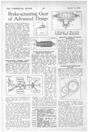
AN improved spreader mechanism for brake shoes is disclosed in patent No. 525,328 by A. Taylor and TaylorJeffreys Patents Holding Co., Ltd., Clarendon Road, London, N.8. The advantages claimed are compactness and the variable-ratio action giving quick presentation of shoes to drum.
Referring to the drawing, an hydraulic piston (3) actuates a pair of bell-cranks (1) which in tarn move plungers (5) to spread the shoes, adjusting screws (4) being interposed. The compression bars (6), as they move outwards, also move nearer the bell-crank pivots, a toggle action which accounts for the fast early motion, reducing the ratio as the movement progresses.
The bell-cranks (1) are pivoted on a pair of plates (2) which have a limited sliding freedom within the casing, and thus a self-compensating action is given between the two shoes. The device is intended to be manufactured as a specialized unit for incorporation in any standard brake.
REAR-ENGINE CHASSIS LAYOUT WITH RUBBER SUSPENSION
ALTHOUGH relating to an improved suspension system, patent No. 524,943 discloses also the latest American ideas on the subject of rearengined commercial vehicles having a
single-tube chassis. The patentee is the B. F. Goodrich Co., New York. The rear-mounted engine (4) drives a twin-wheel axle via an angular transmission shaft (3). The method of attaching the bodywork is shown partially at 6.
The front suspension system employs a rigid fork (1) attached to both wheels, and capable of rising and falling about a pivot (2) mounted on the centre tube of the frame. The rear wheels are similarly suspended, with the addition of a pair of universally jointed drive shafts extending from the differential box (5). The resilient medium in both cases consists of rubber bushings around the pivot pins (2); these bushings allow for the up-anddown motion of the axles.
To deal with the twisting stresses, the housings of the pivots (2) are further pivoted at 7, in a longitudinal direction upon the frame tube. Here, too, rubber bushings are also employed.
EXTRACTING UNBURNT FUEL FROM THE EXHAUST
EXHAUST gases often contain a 1:4quantity of useful fuel, but the high ,proportion of the waste products usually rencleis its recovery unecolona,. A device for separating some of the useful gas from the rest forms the subject of Patent No. 525,103 by G. Pratt and Motor Power Inc., Atlanta, Georgia, U.S.A.
The device takes the place of the conventional silencer. The exhaust products arrive via the pipe (1) and are forced to travel in a helical path by means of a suitable baffle. The heavier cons t ituents, mostly carbon dioxide and water-vapour, are hurled outwardly and escape through ports into an outer chamber (2) leading to the discharge pipe (3). The lighter com ponents, princi 2 pally carbon mon
oxide, tend to be forced to t h e centre and a r e collected by a suction pipe (4) and readmitted to the engine intake. No extravagant claims are made for the efficiency of the device, only an extra 3 per cent, of combustibles being recovered, but the effect on the fuel consumption is said to be most marked,
IMPROVED VEHICLE-WINDOW MOUNTING
PATENT No. 525,322 shows a means for mounting the windows of vehicles, and comes from Leyland Motors, Ltd., and A. Charnock, both of Hough Lane, Leyland, Lancs.
A section of the glass is shown in the drawing, together with the rubber glazing strip, and the metal framing. The glass fits into an upper channel in the rubber strip, whilst the frame projects upwards, as shown at 1, into the rubber to form a watertight joint. At the same time, the window is rigidly supported by the flat bottom face (2). One advantage of this scheme is that it is possible to assemble the window complete before securing it to the• vehicle body.
ELIMINATING TIMING-GEAR RATTLE
HIGH-COMPRESSION valve springs !impose heavy loads on the camshaft, and this load, being continually reversed, is one of the chief causes of wear and chatter of the teeth. To avoid this is the object of a scheme
shown in pafent No. 525,120 by W. Marchant, Doon Cottage, Balfour Road, Weybridge, and Motosacoche S.A., Switzerland.
It is proposed to feed oil tinder pressure to the gears, so that a mass of oil, as distinct from a film, always separates the teeth. The drawing shows a pair of timing gears to which oil under pressure is fed via the duct ' (2). The gears are sunk into their casing, so that they function like a gear pump and some of the oil which is carried round to the outlet side (1) must ultimately pass between the loaded teeth, and maintain a constant pressure against momentary reversals of load. Furthermore, the oil surrounding the gears has a damping effect.