


An American Disc Brake
Page 62
If you've noticed an error in this article please click here to report it so we can fix it.
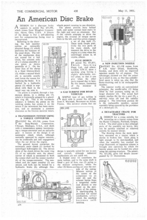
ADESIGN for a disc-type brake appears in patent No. 651,195, which comes from Wingfoot Corporation, Akron, Ohio, U.S.A. A feature of the design is that a self-adjusting unit for compensating facing wear is incorporated.
Referring to the drawing, the hub member carries an outwardly directed flange (1) which performs the function of the usual drum. The rest of the mechanism does not extend for a full circle, but consists only of a C-clamp assembly at one point, as shown • generally at 2. On the inner face of the clamp is a fixed frtetion-block (3), whilst a second block .(4). is movable axially and forms the means for .applying the brake. It is backed by a hydraulic _piston (5) which is supplied. with fluid in the .usual way . via .inlet 6.
The piston is coupled, through a lost:motion device, to a ,sliding pin (7), _which is frictionally gripped by a glandlike ring (8). This is the automatic adjuster; it follows the piston on the working stroke, but arrests it on the return if the movement has been excessive, and so maintains . a constant clearance as the friction material wears.
A TRANSMISSION SYSTEM USING A TORQUE CONVERTER •
PATENT No. 651,316, comes from the Borg-Warner Corporation, Chicago, Michigan, U.S.A., and deals with a transmission system incorporating a torque-converter and an epicyclic gear. A feature of the design is an automatic clutch which, although normally operated by engine rotation, can be artificially put into engagement when the car drives the engine.
The general layout comprises the automatic main clutch (I) worked by centrifugal bobweights (2). The driven plate of the clutch drives the outer ring (3) of an epicyclic unit, the planetcarrier of which is connected to both the output shaft and the output member (4) of the torque-converter. The sunwheel and the input member (5) are joined, and both can be locked by a hydraulic brake (6), although free wheels permit running in one direction.
The planet pinions have helical teeth, and under normal load me■ve to the right and meet an abutment. But if the .vehicle attempts to drive the engine, the reversal of torque moves them to the left, and this action engages a set of dog teeth (7). These teeth couple positively the two parts of the main clutch, and transmit the drive to the engine at a time when the centrifugal action is, of course, absent.
PLUG DESIGN
Ipatent No. 651,851, K.L.G. Sparking Plugs, Ltd., and others, London, S.W.15, show a sparking plug having a slightly deformable central piece, so that it can give when the other parts expand due to heat. By this means, fracturing of the insulator is avoided.
A GAS TURBINE FOR ROAD VEHICLES
A SIMPLE type of gas turbine is 1-1 dealt with in patent No. 651,248, from F. Waloszek, Beaumont en Artois, France. This inventor claims that the
design is specially suited for use in cars and aircraft, although industrial applications are not ruled out.
A bladed rotor (1) constitutes the main turbine, and to the same shaft is fitted a pair of fans, one (2) acting as the mixture compressOr, whilst the other (3) blows cooling air over the outside of the casing. Mixture arrives at the centre of the compressor via an inlet (4) and the exhaust leaves from a tangential outlet (not shown) at one point on the periphery of the casing. A sparking-plug is provided for initial combustion, after which the machine becomes selfigniting. A NEW INJECTION NOZZLE
PATENT No. 651,158 comes from A.B. Atlas Diesel, Stockholm, Sweden, and deals with an improved injection nozzle for oil engines. The advantages claimed are that the actual tip is small in size, so that less cylinderhead space is taken up, also that the flame-receiving end is an exchangeable member.
The injector works on conventional principles, the needle-valve (1) being lifted by fuel pressure acting on its larger diameter (2). The actual fuel supply reaches the tip via a port (3), a one-way valve (4) and the annular passage 5. The lowermost portion (6) is the replaceable member, correct assembly being ensured by the provision of a dowel-pin (7).
A DETACHABLE CRANE FOR TRACTORS
ADESIGN for a crane suitable for mounting on a tractor comes from the Hyster Company, Portland, Oregon, U.S.A. The chief point is that although parts of the assembly are heavy, they can be quickly attached or removed entirely by manual labour.
The drawing shows the main members, mounted on a tractor which is shown in broken line. Each piecs is light enough to be man-handled, and when the assembly has reached the . stage illustrated, an ingenious scheme is brought into operation by which the heavier pieces can be hauled into place using the existing structure. The patent, No. 651,202, gives full details accompanied by 21 illustrations.