


New Technique in Strain Recording
Page 43
If you've noticed an error in this article please click here to report it so we can fix it.
How Direct Readings are Obtained on High-speed Pen Recorders. The Application of Supersonic Wave Beam to ' Flaw Detection
HIGH-SPEED pen recorders are now ,being used in strain gauges in assessing the strains imposed on commercial-vehicle chassis components, under service conditions. These pens replace oscillographs, from which permanent readings are taken by photographic means.
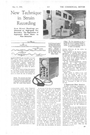
The use of direct-writing instruments for recording variable electrical quantities has, until recently, been confined to cases in which the rate of change was comparatively small; when frequency components exceeding a feW cycles per second were encountered, direct recording was no longer possible, hence the use of photography in conjunction with Duddell or cathode-ray oscillographs. Kelvin and Hughes (Industrial), Ltd., 2. Caxton Street, London, S.W.1, nas developed a moving-coil element which, although it can be driven by a simple valve amplifier, has sufficient restoring torque to enable it to deflect a stylus across its recording paper in as little as milliseconds. The stiffness of the suspension makes the instrument robust and insensitive to external vibration. representative of "The Commercial Motor" recently saw a demonstration of a Kelvin-Hughes four-channel instrument which was installed in a MorrisCommercial 25-cwt. vehicle. The singlechannel and four-channel instruments make their recordings on Teledeltos dry electrolytic paper, which gives an instantaneous and permanent record in the form of a fine black trace on a light grey ground. In the case of the Morris-Commercial, strain gauges were fitted to the frontaxle beam and above and below a chassis side-member midway in the wheelbase. The apparatus was also connected to an accelerometer to record vertical movements. To check the balance of the bridge and amplifier unit a strain gauge was mounted in a rigid structure so that it would not be subjected to any form of elongation.
This check is visual, as correct balance is indicated by a straight line on the recording paper. Reference to a section of a typical recording of the four-channel instrument will also 'show a series of dots on the margins. These are produced by timed electrical impulses, so that the rate of deflection of a member can be read from the record.
The accelerometer is of the movingweight type in which the springmounted weight is suspended between two coils. In effect, the stylus records the position of the weight in relation to the coils, the movement, of course, causing deflection of the stylus by electrical means.
The response of the Kelvin Hughes equipment is uniform from zero to 80 cycles per second and the sensitivity is such that full deflection is obtained for a strain of 30 micro-inches per inch, using strain gauges having a resistance of 2.000 ohms. In the Morris-Commercial vehicle inspected by "The Commercial Motor," which is being used for demonstration purposes, two 12-volt heavyduty batteries were installed to drive a motor generator. The equipment, however, is designed to operate off ac. mains supply.
Paper speed is either 5 cm. and 15 cm. per second, or 2.5 cm.. and 7.5 cm. per second. With a fourchannel instrument, the pen or stylus amplitude is plus or minus 7.5 mm.. and in the case of a two-channel instrument this is increased to plus or minus 12 mm.
A.Supersonic Flaw Detector
Another interesting instrument for which the Kelvin I•lughes organization is responsible is a supersonic flaw detector. The principle upon which it works is that a transmitter probe directs a supersonic wave beam in the form of pulses of short duration.
If the specimen under test be perfectly sound, the propagation of this supersonic energy is reflected only by the base of the material. The reflected energy picked up by the receiver-probe equipment shows only transmission and base indications on the cathode-ray oscillograph.
Should there be any defect between the surface and the base of the material, a certain amount of the transmitted energy will be reflected in advance of the base echo, and such reflection ilt indicate itself by a pre-deflection of the trace. As the scale of the cathode-ray tube is linear, the position of the flaw in relationship to its depth from the surface of the material can readily be ascertained. This equipment was • designed to detect flaws to a depth of about 12 ft. in steel. This can be extended to 25 ft.