


A Tool for Inserting Valve Guides
Page 44
If you've noticed an error in this article please click here to report it so we can fix it.
A Resume of Patent Specifications That Have Recently Been Published
• THE usual valve guide is held in the • 1 cylinder by means of a forced fit, and is often difficult to insert with out damage. A tool of use in this respect forms the subject of patent No. 567,855, from Q. Clanccy, 61, New Street, West Brothwich, The tool consists of a bored body (1) having three feet which gre ground • square with the bore. A keyed bolt and its nut (2) provide the necessary force, which is applied to the guide via a screwed-in mandrel (3) made to fit the valve guide. In cases where the threefooted body cannot be used, an alternative cone member is supplied; this settleS 'itself down in the valve seating. The tool can 'also be used as an extractor by suitably reversing its action, AN IMPROVED MOLE-DRAINAGE PLOUGH
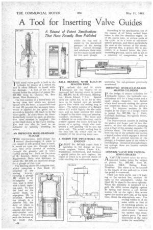
THE conventional mole-plough has several disadvantages; it tends to run deeper in soft ground than in hard, It leaves an open slot through which rain runs away instead of soaking through the ground, and it wears rapidly.during use. Such are the views, of R. Kendall, Millow Lodge Farm, Biggleswade, Beds, who discloses, in patent No. 567,626, an improved design for a plough of this type. The drawing shows the complete tool, which comprises a thin blade (I)
attached to the • towing . beam, carrying a: plough (2) which is of
rectangular section, and is fitted with a-bard, tapering, nose. To ease the load on „the carrier blade, an edge-piece (3.) is provided. Behind the plough is a follower (4), the. duty of which is to force . the rect7 angular slot into a semi-circular arch Shape. This action seals the bottom of the Wade slot,
BALL BEARING WITH BUILT-IN -SEALING RING
TO exclude dirt and, to retain lubricant ale the 'objects' of an improved hall bearing shown, in patent No 567781, by R. Stevenson, ,Baring
'ton,, Rhode Island, U.S.A. Special races are called .for, in so far as they have to be formed into an annular groove into which the sealing Ying is fitted. The latter consists of a flanged sleeve (1). whieh'tightlyfits the outer race, and an inner member (2) which is keyed to the.outer ring and retngin.s, therefore, • stationary. .• The inner part is slidable in an axial direction, and is pressedagainst the inner hall-race by means of a spring, which arso compresses a soft _packing (3) to seal tlie Outer end, The actual sealing face is the thin rini (4) :which • ruhS the " shoulder of the revolving inner race'.
A PISTON FOR' TWO-STROKE OIL — RNGINES
pATENT No. 567;825 comes from a specialist in the design of two. stroke. engines, Sulzer 'Freres S.A., Winterthur, Switzerland, and discloses a -special piston for suCh engines, the object of which is to prevent excess oil from reaching the combustion space. According to the specification, one of the causes of oil -being sucked from below is that the clearance region (I) of the piston may, at certain parts of the cycle, be in a state of sub-atmospheric pressure; and this is particularly, the case at the bottom of the stroke. To prevent this, a groove (2) is provided; it is located below theporttraversing portion, and is said to act as a reservoir of compression and so
neutralize the sub-pressure previemaly mentioned.
IMPROVED HYDRAULIC-BRAKE
MASTER-CYLINDER . IN the design of master cylinders for l'hYdraulic brakes, the hydraulic considerations call for a long stroke and 'a small piston diameter, two factors which tend towards making the piston rd somewhat flimsy for the driver's foot. To improve matters in this respect is the object of a design shown in patent No. 567,764, -fiy J. Pratt, Guildhall Buildings, Navigation Street, ,Birmingham.
The improvement consists in making the' piston rod larger and of two diameters, so that the effective. pumping. area:is that of the annular shoulder (I) :between them.: The sal] end projects ,. from the end of the cylinder: and carries a keyed washer which engages a slotted guide (2) to .prevent -rotation of the' plunger; a frequent cause af the .driver's foot slipping; Instead of internal retracting springs, these are located. outside the cylinder.
CONTROL VALVE FOR VACUUMSE RVO BRAKES AVACUUM control valve for servooperated brakes forms the subject of patent No. 567,687, from M.
Johnson, 134-6, Ealing Road, Wembley. The valve is to be located in the length of the pull-rod to which the pedal is connected. '
• There are three ports, one (1) leading to the suction line, another (2) open to the atmosphere, whilst the third (3) is piped to the servo cylinder. When the assembly is subjected to a pull, the slider moves slightly against its spring and moves a soft rubber washer (4), to the right; this action opens the suction port and, at the same time, closes the atmospheric vent. The sealing washer is Of the -same width as that of its enclosing grtiove, so that there'is n.o risk of al short-circuit between -the suction andatmospheric ports. The small movement of the valve makes for sensitivity: