


Easily Produced Constant velocity Universal Joint
Page 32
If you've noticed an error in this article please click here to report it so we can fix it.
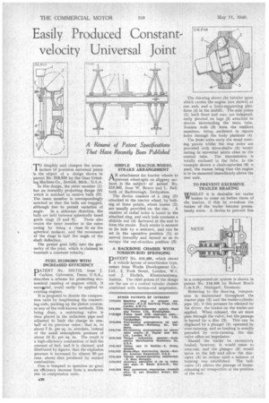
simplify and cheapen the manufacture of precision universal joints is the object of a design shown in patent No. 518,838 by the Gear Grinding Machine Co., Detroit, Mich., U.S.A. In this design, the outer member (1) has an inwardly projecting flange (4) which is notched to receive balls (3). The inner member is correspondingly notched so that the halls are trapped, although free to permit variation of angle. In a sideways direction, the balls are held between spherically faced guide rings (2 and 5). These also centre the inner member in the outer easing by being a close fit on the spherical surfaces, and the movement of the rings is half the angle of the shaft deflection.
The patent goes fully into the geometry of the joint, which is claimed to transmit a constant velocity.
FUEL ECONOMY WITH INCREASED EFFICIENCY DATENT No. 518,712, from J.
Ca.rlson, Galveston, Texas, U.S.A., describes a scheme for promoting economical running of engines which, if succeisful, could easily be applied to existing engines.
It is proposed to double the compression ratio by lengthening the connecting rods, packing up the piston crowns, or any of the well-known methods. This being done, a restricting valve is then placed in the induction pipe and adjusted to limit the charge to onehalf of its previous value: that is, to about 7 lb. per sq. in. absolute, instead of the usual atmospheric pressure of about 14 lb. per sq. in. The result is a high-efficiency combustion of half the amount of fuel, and it is claimed, and illustrated by figures, that the explosion pressure is increased by almost 50 per cent. above that produced by normal combustion.
One is tempted to question so great an efficiency increase from a moderate rise in, compression ratio.
SIMPLE TRACTOR-WHEEL STRAKE ARRANGEMENT
AN attachment for tractor wheels to prevent wheel-spin on slippery surfaces is the subject . of patent No. 518,805, from W. Bower and L. Ball. both of Barlborough, Derbyshire.
The device consists of a ring (5) attached to the tractor wheel, by bolting at three points, where bosses (2) are usually provided on the rim. A number of radial holes is bored in the attached ring, and each hole contains a slidable rod (4) flattened at the end to form the strake. Each strake is secured in its hole by a setscrew, and can be set in the operative position (1) or moved inwardly and turned so as to occupy the out-of-action position (3).
A BACKBONE CHASSIS WITH TORSION-ROD SPRINGING
PATENT No. 515,485, which shows a vehicle layout of unorthodox type, comes from Works Development Co., Ltd., 2, York Street, London, W.1. and J. Ehrlich, Klosterneuburg, Austria. The chief points of the design are the use of a central tubular chassis combined with torsion-rod suspension.
The drawing shows the tubular spine which carries the engine (not shown) at one end, and a body-supporting platform (4) in the middle. The axle yokes (1), both front and rear, are independently pivoted on lugs (2) attached to sleeves surrounding the main tube. Torsion rods (8) form the resilient members, being anchored in square holes through the body platform (4).
The front axles carry the usual steering pivots whilst the tear axles are provided with drive-shafts (5) terminating in universal joints close to the central tube, The transmission is totally enclosed in the tbbe; in the example shown a chain-sprocket (6) is used, the reason being that the engine is to be mounted immediately above the rear axle.
TO PREVENT EXCESSIVE TRAILER BRAKING WHILST it is desirable for trailer W brakes to come on before those of the tractor, if this be overdone the brakes of the trailer become prematurely worn. A device to prevent this
in a compressed-air system is shown in patent No. 518,506 by Robert Bosch
G.m.b.H., Stuttgart, Germany. • Referring to the drawing, compression is maintained throughout the tractor pipe (2) and the trailer-cylinder pipe (4); if this pressure he released by the driver, the brakes on the trailer are applied. When released, the air must pass through the valve, but the passage is barred by a disc (3). This can be displaced by a plunger (5) operated by over-running, and as braking is usually preceded by over-running, the disc valve offers no impedance.
Should the trailer be excessively braked, however, it would cease to over-run, and the plunger (5) would move to the left and allow the discvalve (3) to reclose until a balance of braking was established. The hallvalve (I) allows the passage of brakereleasing air irrespective of the position of the rest.