


From Engine to Axle,
Page 15
Page 16
If you've noticed an error in this article please click here to report it so we can fix it.
Following the recent papers read before the Institution of Automobile Engineers, which have dealt respectively with rear axles and engines, a third has now been read dealing with those parts of the transmission which were not included in the previous two reviews. Major Shilson, the author, 'disclaims any intention to "present any new features or enunciate any new theories." but he has dealt with his subject in an informative manner, and we therefore reproduce the paper in instal, merits as opportunity occurs. This instalment follows that on page 198 of last issue.
A Paris-bus Gearbox.
This gearbox *has been adopted by the Paris General Omnibus Co. to the exclusion of the sliding type, which wore out quickly under the excessive changing which is necessary in city traffic. The Paris omnibus, being of the single-deck type to carry about forty passengers, is very much heavier than the Lon% don type of omnibus, while the engine is of almost the same power and thus throws more work on the gearbox.
The French War Office are now specifying this gearbox to be fitted to all heavy transport wagons where circumstances and the design of chassis will permit, All Gears in Mesh.
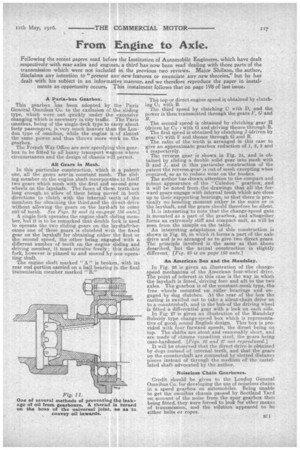
In this particular construction, which is a patent one, all the gears arek in constant mesh. The sliding member on the engine shaft incorporates in Itself two gears which mesh with the first and second gear wheels nn the layshaft The faces of these teeth are long enough.. to allow of their being moved in both directions to clutch with the internal teeth of the members for obtaining the tliirdiand the direct drive without allowing the gears on the layshaft to come out of mesh. See Figs. 28 and 24 on4lage 156 ante.] • A single forkOperates the engine shaft sliding member, but it is to be remarked that double fork is used to operate the two sliding gears on the layshaftdaecause one of these gears is clutched with the fixed gear on the layshaft for obtaining either the first or the second speed, the other being engaged with a different number of teeth on the engine sliding and driving member, it must revolve freely_; this double fork, however is pinned to and moved by one operating shaft The engine shaft marked " A " is broken, with its rear end portion carried on a ball bearing in the final transmission member marked "B."
The top or direct engine speed is obtained by clutching CI with B. The third speed by clutching C with D, and the power is then transmitted through the 'gears F, G and The second speed is obtained by clutching gear IT (driven by CT ) with G and driving thence through B. The first speed is obtained by clutching J (driven by gear C) with F and thence through G and B. The ratio of the teeth is arranged in this case to give an approximate• gearbox reduction of 1, 2, 3 and 4 respectively.
The reverse gear is shown in Fig. 24, and is obtained by sliding a double solid gear into mesh with B and J, and in this particular construction of the patent the reverse, gear is out of mesh excepting when required, so as to reduce wear on the knishes.
The author has drawn attention to the compact and robust appearance of the " Caledon " gearbox, and it will be noted from the drawings that all the forward gears engage with internal teeth which are close up to their supporting bearings, so that there is practically no bending 11101111eat either in the main or in the layshaft, and the gears should therefore be silent. It is interesting to note that the change-speed gate is mounted as a part of the gearbox, and altogether forms an extremely stiff and compact unit, as will be seen from the sample on the table.
An interesting adaptation of this construction is shown in Fig. 25, in which it forms a part of the axle drive and is so arranged as to give two direct gears. The principle involved is the same as that above desvibed, but the actual construction is slightly different. [Fig. 25 is on page 156 ante.] An American Box and the Mandslay.
In Fig. 26 is given an illustration of the changespeed mechanism of the American four-wheel drive. The point of interest in this case is the way in which the layshaft is fitted, driving fore and aft to the two axles. The gearbox is of the constant-mesh type, -the free whe.els mounted on roller hearings and engaged by dog clutches. At the rear of the box the casting is swelled out to take a silent-chain drive on to a countershaft, and in the hub-of the driving wheel is fitted a differential gear with a lock on each side.
In Fig. 27 is given an illustration of the Maudslay Subsidy type change-speed box which is representative of good. sound English design. This box is provided with four forward speeds, the direct being on top. The shafts are stout and reasonably short, and are made' of chrome vanadium steel, the gears being. ease-hardened. [Figs. 26 and 27 not reproduced]
It will b obServed that the direct drive is obtained by dogs instead of internal teeth, and that the gears on the countershaft are connected by slotted distance pieces instead of through the medium of the castellated shaft advocated by the author.
Noiseless Chain Gearboxes.
Credit should be given to the London General Omnibus Co. for developing the use of noiseless chains in a speed gearbox on automobiles. teing unable to get the omnibus chassis passed by Scotland Yard on account of the noise from the spur gearbox then being fitted, they were forced to look for other means of transmission, and the solution appeared to be either belts or ropes.
Difficulty with Chain Gearboxes.
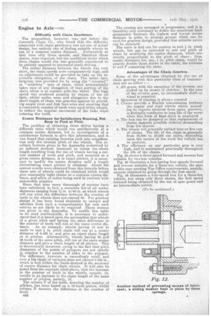
• The proposition, however, was ppt before the Coventry Chain Co., who found that the difficulty connected with chain gearboxes was not one of actual_ design, but, entirely one of finding suitable wheels to run at a common .centre distance. Fortunately at that time only three speeds, and therefore three chains, were required, but the conditions Under which these chains would run was generally considered to be entirely opposed to successful chain driVing.
The centre distance between the wheels was very short, the chain speeds were comparatively high, and no adjustment could be provided to take up the inevitable elongation of the chain. The latter fact, hoNyever, was provided for by using the "inverted" or 'k` noiseless" type _of chain, which automatically takes care of any elongation 'of that portion of the chain which is in contact with..the wheel. The high speed was rendered possible by reason of the oil bath, whilst undue wear and elongation due to the short length of chain was guarded against by providing ample rivet and link face area, and ensuring that a reasonable number Of teeth were used in.the wheels, to reduce the angular movement of the links when entering the teeth.
Centre Distances for Satisfactory Running, Not Easy to Find at First.
The problem of obtaining three drives having a different ratio which would run satisfactorily at a common centre distance, led :to investigation of a satisfactory formula to give this information, and it was found that existing formuhe took into consideration only thecircular pitch of the wheels. The resultant formula given in the Appendix is,derived by an indirect method, inasmuch as unless the chain length resulting from the u-se of wheels having a certain number of teeth and pitch, and mounted at a given centre distance, is in exact pitches, it is necessay to modify the centre distance until a length necessitating exact pitches is obtained. About 500 correct results were obtained from this formula before three sets of wheels could be obtained which would give reasonably tight chains at a common centre, distance, and allow of ratios being used to conform with automobile practice. Since that time many thou sands of centres have been tabulated, in fact, a complete list of all centre distances ranging from 11 in. to 00-in, at which wheels will run when the difference-between ,the number of teeth in the wheels,does not,exceed 80. For gearbox design it has been found desirable to extract and tabulate from such a comprehensive list only such centres as are likely to be required. These centres• are given in the Appendix.To enable this table to be read intellectually, it is necessary to understand that it is based upon the assumption that wheels of a given pitch and having the same • difference in the number of teeth will run at the same centre distance, As an example, wheels having 12 and 24 teeth to suit in. pitch chain will run at a centre distance of 6.429 in. and give an exact chain length or 44 pitches. Alternatively, wheels having 24 and 36 teeth of the same pitch, will run at the same centre diatance and give a chain length of 56 pitches. This is theoretically Incorrect, owing to the fact that pitch diameters of the points of -polygons are not strictly in relation to the number of sides to the polygon. The difference, however, is exceedingly small, and over a big range of variance does not exceed 0.002 in., which is well within the limits desired in the accuracy of centre distance for chain wheels. It will also be noted from the example citeclabove, that the increase in the number of teeth in the wheels, namely, 12, results in an increase in the chain length of the same number of pitches, namely, 12. , The column P of the table, denoting the number of pitches, has been based on a I2-tooth pinion, whilst column D denotes the difference -in the number of
teeth. , 33N
The centres are arranged in progression -and it is therefOre only necessarY te define the maxiinuna EMU permissible between the highest and lowest centre distance in order to arrange groups which can be used for gearbox design, provided that suitable ratios can be obtained. The table is laid out for centres to suit )2 in. pitch wheels, but can be extended to suit any pitch of chain by modifying the 'centre distances, which "are strictly proportional to the pitch of chain ; thus, centre distances for say, 1 in. pitch chain, wculd be exactly double those shown in the table, the columns D and P remaining the same.
Advantages Of the Chain Gearbox.
Some of the advantages obtained by the use of chain gearing with this particular Class of transmission are as follow :— 1. All gears, with the exception of the reverse, are picked up by means of clutches. In the case of the reverse gear, no intermediate shaft or wheel is required. 2. Quietness of running is always ensured. _ 3. Chains provide a flexible transmission between the engine and road wheels which, according to reports received from many quarters,. is distinctly conducive to long life of the worm when this form of final drive is employed. 4. The box can be designed so that replacement of chains isamade possibla without dismantling from the chassis.
5. 'The wheels will generally outlast four or five sets of chains. The life of tha chain is ;generally from 30,000, to 50,000 car miles, depending upon the nature of the work the vehicle has to perform.
6. The efficiency on any particular gear is very high, and is maintained practically throughout • the life of the chains. • Fig. 28 shows a three-speed forward and reverse box suitable for two-ton vehicles.
Fig. 29 illustrates a box having four speeds forward and reverse suitable for a three-ton vehicle, the gate in this case meeting War Office requirements, namely, reverse obtained by going through the first speed. Fig. 30 illustrates a four-speed box for a three-ton vehicle, butusing only three chains, the first speed forward being obtained by the use of spur gears and an intermediate pinion.