


Torsion Control for Powered Steering A POWER-ASSISTED steering gear is
Page 62
If you've noticed an error in this article please click here to report it so we can fix it.
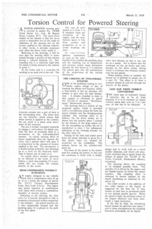
covered in patent No. 720,888 (Ford Motor Co., Ltd., 88 Regent Street, London, W.1). The most novel feature of the scheme is that the servo action is dependent not on the angle of deflection of the steering but on the torsion applied to the steering column; in other words, it provides assistance only when the driver really needs it. Referring to the drawing, it will bo. seen that the steering effort is transmitted through a portion of the column having a reduced diameter (1). Surrounding this is a relatively rigid tube (2) which is firmly pinned to the column at point 3.
At the lower end is a cross-pin (4) working in an axial slot in the rod. The cross-pin extends into a pair of slots in the surrounding tube. The latter slots are cut helically, which means that when torsion is applied to the column, the net result is a small axial movement of the cross-pin.
The pin is further extended outwards to engage a valve-sleeve (5) which controls the flow of hydraulic fluid to a servomotor in the well-understood manner. In action, steering effort of minor magnitude does not operate the valve, but a greater effort will open it in proportion to the amount of torsion applied to the rod. The servomotor is a double-acting hydraulic ram thrusting on to a lever on the drop-arm shaft. This is shown out of scale at 6.
To enable direct manual operation to be effected in the event of servo failure, a slack dog-coupling (7) is provided; this can couple the column directly to the worm.
HIGH COMPRESSION WITHOUT KNOCKING
A' engine designed to use volatile fuel with a compression ratio of up to 12 to 1 forms the subject of patent No. 723,711 (Texaco Development Corp., New York, U.S.A.). The engine uses petrol injection in combination with rapid swirl around a combustion chamber of smooth outline.
Referring to the drawing, the inlet valve (1) is heavily shrouded so that it produces a directional airflow tangential to the cylinder. The petrol injector (2) is also tangentially located and the sparking plug (3) is placed in the path of the fuel spray. The rate of swirl aimed at is from 5 to 8 complete turns per revolution of the engine, and the combustion space is free from corners and projections so as to avoid breaking the swirl.
In .operation, ignition commences as soon as the combustible front reaches the sparking plug, and the resulting rise in temperature and pressure cannot cause detonation because the fuel burns as it is injected. The patent goes into the mathematics of the proportions of the various dimensions.
THE COOLING OF TWO-STROKE • ENGINES
ONE of the problems arising in twostroke engine design is that of keeping the piston cool because, unlike a four-stroke, it has no alternate idle strokes to give time for heat dissipa
tion. A scheme intended to help in this respect is disclosed in patent No. 723.324 (J. Jameson, " Brockhamburst," Betchworth, Surrey).
The drawing shows a section of the proposed engine, which is provided with a two-diameter piston for both the power cylinder and the charging-pump cylinder. The working cycle is as follows: On the down stroke, air is drawn into the annular space 1 created by the descent of the large piston (2). On the succeeding up stroke, the air is transferred to duct 3 for subsequent admission to the working cylinder via the inlet valve (4).
Timing of the inlet and outlet ports from the pump chamber is given by a thin sleeve valve (5), worked by eccentrics on the crankshaft. The exhaust leaves via the cylinder-wall ports (6).
The basis of the patent is the means used for cooling the piston; to this end the crankcase is fitted with a simple valve (not shown), so that it, too, can act as a pump. Air is drawn into the crankcase on the up stroke and compressed on the down stroke, during which it is forced into intimate contact with the hot piston.
. When bottom stroke is reached, the heated air is allowed to escape out of a port (7). The effect is to blow a constant stream of cool air through the interior of the piston.
LESS SLIP FROM TORQUE CONVERTERS
THE usual type of hydraulic torque converter has to be of large diameter if it is to transmit its torque without undue slip; even so, 2 to 3 per
cent. of slip has to be tolerated. A design said to work well on a much smaller diameter, and which will practically eliminate slip at speed, forms the subject of patent No. 722,287 (J. M. Voith, G.m.b.H., Heidenheim (Brenz), Germany).
The drawing shows the coupling in its simplest possible form. The impeller (I) is driven by the engine and the bladed runner (2) forms the output member. The coupling effect is obtained in known manner by the liquid circulating as indicated by the arrow (3).
The chief novelty is the addition of fine solid matter to the liquid, as suggested by the dots (4). It may consist of steel shot or powdered metal of any desired specific gravity. When the speed is high, the particles collect at the largest diameter and form practically a rigid connection.
If the slip be high, the circulating liquid washes the particles into space 5, and in these circumstances the coupling functions principally on its liquid.