A Two-way Self-energizing Brake System
Page 54

If you've noticed an error in this article please click here to report it so we can fix it.
NAANY self-energizing brakes of the W/leading-shoe type give an increased braking in one direction, but are not so effective in reverse. .A brake which is equally active in either direction forms the subject of patent No. 597,358, from J. Pratt, Guildhall Buildings, Navigation Street, Birmingham.
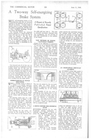
The drawing shows the proposed scheme applied to a vehicle having one front axle and two at the rear, all of which are .braked. On the front brakes (1) each shoe is a leading shoe in the forward sense, and the rear axle (2) is similarly arranged, so that a powerful effect is obtainable in the forward direction.
1 he forward axle (3) of the rear set is fitted with pairs of oppositely directed leading shoes, but in this case the hydraulic expanders are provided with two sizes of piston, the. larger of which works the reverse-leading shoes (4). By this means, although there are only two leaders in reverie, their functioning is materially increased by the greater force arising from the larger piston.
IMPROVEMENTS IN WINCH MOUNTING WHEN a hauling winch is fitted to W a vehicle, it is usually necessary to provide a complex system of guide pulleys if it be desired to allow the cable to haul in any direction. To simplify matters in this respect is the aim of a scheme shown in patent No. 597,782 by Crossley Motors, Ltd., and W. Owen, both of Gorton, Manchester.
The 'drawing shows part of a side view of the vehicle, in which 1 is the winding drum of the winch. The cable is taken first through a tensioniqg device (2) then over a pulley (3) to a point under the vehicle frame. Here it runs through the centre of a free turntable (4) and then passes around a pulley (5).
The bearings for the pulley are mounted on the turntable so that it :an swing freely in any direction that the cable pull may take it. Not only is universal movement obtained from this arrangement, but the low-line of pull adds considerably to the stability of the vehicle.
NEW METHOD OF FIXING VALVE-SEAT INSERTS
ONE of the difficulties in connection with the use of inserted alloy valve seats is that their thermal expansion usually differs from that of the surrounding metal, so that looseness eventually develops. To prevent this is the object of an improvement in fixing methods shown in patent No. 597,398, by Thompson Products Incorporated, Cleveland, Ohio, U.S.A.
Referring to the drawing, the seating is made in two parts—an outer ring (1) and an inner member (2). The outer piece is preferably made from the same metal as the surrounding casting, but the inner ring is made from an alloy chosen for its heat-resisting properties.
The two are united by the saw-toothsection teeth (3), which permit a measure of expansion and contraction without straining any of the mating surfaces.
The assembly of the two parts is achieved by first making them so that one will fit within the other, and then by a press operation, forcing either the outer one inwards, or expanding the inner one. The teeth are shown somewhat larger than their true scale size; in practice a depth of approximately 0.03 in. would be used.
A SERVO MOTOR FOR STEERING GEAR INTENDED primarily for use with powered steering mechanism, a hydraulic servo cylinder is shown in patent No. 598,087 by Integral, Ltd., and R. Worlidge. both of Power Road, Chiswick, London, W.4. One advantage of the scheme is that, as a stationary cylinder is employed, there is no need for flexible oil pipes with their attendant troubles.
Referring to the drawing, (1) is the output member which operates the road-wheel steering. The steering wheel works an inner member (2), moving it to the right or left, as the case may be. This member has slight end play in its casing, and is normally held in the mid-position by a pair of springs (3), one mounted at each end.
When the steering wheel is turned. the end play moves a valve member (4) which, by suitable port arrangements, admits fluid under pressure to one side or the other of an annular piston (5). The piston is directly connected to the output member, and faithfully follows the action of the control valve.
The valve is of the self-lapping type, and always tomes to rest in an "off" position. Should the hydraulic power fail for any reason, the steering could still be operated by manual effort after the slight end play has been taken up in the direction of movement.
AN EIGHT-SPEED EPICYCLIC GEARBOX _A GEARBOX giving eight speeds is ri stiown in patent No. 597,814, by C. Clutton and J. Edisbury, Hooton Farm, Hooton, Cheshire. These inventors state that whilst eight speeds are advantageous, the means for selecting 'them may become confusing to the driver, and the chief point of the scheme is to simplify this matter.
The gearbox shown is a three-stage epicyclic unit of the Cotal type, with the three stages compounded in series.
Calling the individual ratios A, B and C, there are eig,ht possible overall ratios, I to 1, A, B, C, AB, BC, AC and ABC. The inventors consider that the usual "H" type of gate, with its four speeds, is sufficient for the driver to handle at any moment, and so a standard gear lever is provided.
This gives normal control of four speeds, but when the other four are needed a master switch is used to effect a group change. The gear shown, is electrically operated by magnets (I) which, when energized, grip one of the epicyclic elements. Although the gear lever resembles the usual type, it is, in reality, an electric selector switch.


