


Disc Brakes for Road Vehicles
Page 58
If you've noticed an error in this article please click here to report it so we can fix it.
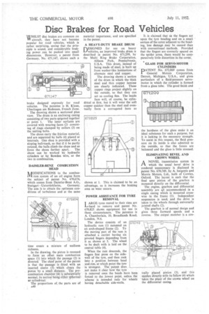
WHILST disc brakes are common on TV aircraft, they have not become popular for road vehicles, which is rather surprising, seeing that the principle is sound, and considerable braking power can be packed into small dimensions. However, a patent from Germany, No. 671,147, shows such a
brake designed expressly for road vehicles. The patentee is H. Klaue, Uherlingen am Bodensee, French Zone.
The drawing shows a sectioned plan view. The drum is an enclosing casing consisting of two parts spigoted together at point 1. The inner surfaces are covered with wearing faces (2) consisting of rings clamped by collars (3) on the uniting bolts.
The shoes carry the friction material, and are separated by balls (4) placed at intervals. One shoe is provided with a sloping ball-track, so that if it be partly rotated, the balls climb the slope and so force the shoes further apart. The shoes can be worked by hydraulic cylinders or by Bowden wire, or the two in combination.
DAIMLER-BENZ COMBUSTION HEAD NAODIFICATIONS to the combus11'1 tion system of an oil engine form the subject of patent No. 670,674, which comes from Daimler-Benz A.G., Stuttgart Unterttirkheim, Germany. The aim is to obtain the optimum conditions of turbulence and at the same time create a mixture of uniform richness.
In the drawing, the piston is recessed to form an offset main combustion space (1) into which the passage (2) is directed. The chief point of the patent is that the passage is fitted with an inserted sleeve (3) which clears the piston by a small distance. The precombustion chamber (4) is substantially normal, its section being either spherical or cylindrical.
The proportions of, the parts are of A40 material importance, and are specified in the patent.
A HEAVY-DUTY BRAKE DRUM
DESIGNED for use on heavy L./vehicles, an improved brake drum is described in patent No. 671,299, by the Multi Ring Brake Corporation, Allison Park, Pennsylvania, U.S.A. This drum, instead of being made of steel, is built up from washer-like laminations of alternate steel and copper.
The drawing shows a section of the drum in which the thick steel and thin copper larninEe are clearly indicated. These copper rings project slightly on the outside, so that they can act as cooling fins. The inside face will, of course, be cylindrical at first, but it will wear the soft copper quicker than the steel and eventually form a corrugated bore as
shown at 1. This is claimed to be an advantage, as it increases the braking area as wear occurs.
POWER ASSISTANCE FOR TYRE REMOVAL
LARGE tyres rusted to their rims are LARGE
to remove and patent No. 670,825 shows equipment for use in these circumstances. The patentee is A. Chamberlain, 10, Broadlands Road, London, N.6.
The device consists of an hydraulic ram (1) mounted on an arch-shaped frame (2). To the moving part of the ram is attached a .carrier having six pivoted fingers depending from it as shown at 3. The wheel to be dealt with is laid on the central table (4).
When the ram descends, the fingers first press on the sidewall of the tyre, and then rock into a position between head and rim, at which point the tyre is strongest. The patent does not make it clear how the tyre is removed once the beads have been forced to the lowest point, unless the scheme is intended only for wheels having detachable side-walls. It is claimed that as the fingers act upon the tyre beading and on a small section of the cover adjacent to the beading, less damage may be caused than with conventional methods. Provided that the fingers are correctly spaced on the spider arms, there would be comparatively little distortion in the cover.
GLASS FOR SERVO-MOTOR CYLINDERS
PATENT No. 672,069 comes from General Motors Corporation, Detroit, Michigan, U.S.A., and gives particulars of a fluid-pressure servomotor in which the cylinder is formed from a glass tube. The good finish and
he hardness of the glass make it an ideal substance for such a purpose, but it is lacking in the necessary strength. To assist in this respect, the fluid pressure on its inside is also admitted to the outside, so that the forces are balanced and the glass is little stressed.
ELIMINATING BEVEL AND CROWN WHEEL
ANOVEL transmission system in which the usual bevel drive is rendered unnecessary is disclosed in patent No. 670,749, by A. Issigonis and Morris Motors, Ltd., both of Cowley, Oxford. The layout is such that the final spur pinion of the gearbox is mounted directly on the differential.
The engine, gearbox and differential assembly are 411 accommodated in a single casing which is mounted crosswise in the frame (1). independent suspension is used, and the drive is taken to the wheels through universally jointed shafts (2).
The gearbox is of normal design and gives three forward speeds and a reverse. The output member is a cen trally placed pinion (3), and this meshes directly with its fellow (4) which takes the place of the crown wheel on the differential casing.