


An All-mechanical Servo Device for Brakes
Page 36
If you've noticed an error in this article please click here to report it so we can fix it.
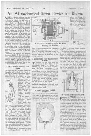
ASERVO device suitable for the operation of power-assisted brakes, is shown in patent No. 557,569, by Automotive Products Co., Ltd., and G. Gates, both of Tachbrook Road, Leamington Spa. The device is entirely mechanical and works in an enclosed bath of oil. Referring to the drawing„ the shaft (3) is driven from the gearbox of the vehicle and carries a series of discs (5) mounted on splines. Ia4rspaced with these is a second set of larger discs (7), mounted on rods attached to a free carrier (4). These discs form the driven member and tend to rotate when end pressure is applied by the small hydraulic cylinder (8), which is piped to the driver's pedal.
Integral with discs 7 is a helical cam (6 and 1), which, as it rotates, -imparts an amplified force to the roller-ended piston rod (10) •of a master hydraulic cylinder (9). A roller-bearing abutment (2) relieves the cam of all end
thrust. .
Actually, the basis of the patent is the shape of discs 7; these are made of metal and are provided with circumferential corrugations in the part that contacts discs 5. The latter are made of friction material. The patent also claims the use of the same type of disc in the construction of clutches.
A DUAL-RATIO HAND.BRAKE LEVER
1N every-day use, the hand brake has usually only to hold the vehicle on the level or on slight gradients, and it "can, therefore, be designed with a moderate degree of leverage. In a real emergency, however, some extra leverage would be welcome and, with this in view, a scheme of dual levers is shown in patent No. 557,692, by Bendix, Ltd., and H. Keen, both. of King's Road, Tyseley, Birmingham,
In this system a pair of levers is employed, being pivoted on t h e same shaft and located side by side. The drawing shows the two levers, one (1) being for normal use, whilst the other (6) is reserved for emergencies As shown, the normal brake is " on," the other one being in the " off " position In ordinary operation. lever 1 pulls on a link (2), which swings a small lever (3) about the temporarily 'stationary pivot . (5), thus pulling on the brake rod (4). Having reached the maximum pull by this means, if further force be required, the second lever (6) is moved. This, in turn, moves the pivot (5) towards lever 1 and so gives a short-range, but power ful, pull. , The advantage of the scheme is that the secondary pull comes into operation only after the ,first lever has taken up all slack, clearance and wear, so that none of the higher leverage is wasted in this way. Interlocks are provided to* prevent operation of the levers in the wrong sequence.
A DEFROSTER FOR -WINDSCREEN WIPERS 'TO remove ice and snow from the L windscreen is the object of an attachment shown in patent N. 557,668, by J. Taylor, Hall End Cot
tage, Hall End, Wednesbury. The drawing shows a standard oscillating wiper blade (2), with the addition of a pair of perforated pipes (1), through which hot air is forced. The air is drawn through a muff surrounding the exhaust manifold and is delivered to the • wiper via a fleXible pipe (3). The Air is propelled by a small pump operated by the suction of the engine.
The patent also coi:ers the use of jets of.steam instead of air, the steam being formed by forcing water into the exhaust-heated muff.
A BEAD LOCK FOR OUTER COVERS I F a vehicle be run on a deflated tyre, the creep of the cover on the rim will cause considerable damage to the tube.; sometimes this occurs so quickly that the tube is ruined in the short time taken to bring the vehicle to a standstill. To prevent this is the objectof a cover-locking device shown in patent No. 557,665, by the Dunlop , Rubber Co,, Ltd., 1, Albany Street, London, N.W.1, and others.
The drawing shows a cross-section of the cover and rim, With the locking
device in position. It consists of a metal band which completely surrounds the rim and is keyed against rotation by a boss engaging with the valve hole in the rim; the section shown is taken at this point. The metal band is provided with down-turned edges, which press on the tyre bead and force it into tight contact with the corners of the rim. The device is suitable for rims having only one detachable side wall.
PROGRESS IN ROTARY-VALVE DESIGN
PATENT No, 557,565 comes from F. .Aspic, 149, Walmersley Road, Bury, and deals with improvements to this inventor's well-known rotary valve. The conical shape of this valve lends, itself to effective seating, but, if excessive I)1 re be applied, considerable friction can be set up. To maintain the pressure at the optimum sealing value, hut to prevent overload, is the object of the improvements.
In the drawing, 3 is the revolving conical valve, carried by roller bearings and driven from above by a spur gear (1). The-valve seats in a plug member (2), which is made to be a sliding fit in an upward extension of the cylinder. The sealing pressure is governed entirely by a compression spring (4), if the valve be slightly moved upwards by the combustion gases, the plug goes with it, thus avoiding excessive pressure between the sealing faces.