


THE ACTION OF A MODERN CARBURETTER.
Page 20
If you've noticed an error in this article please click here to report it so we can fix it.
How the Main and Compensating Jets Operate in the Zenith Device.
(IN MANY occasions the Zenith CarkJ burettes Co., Ltd., 40-42, Newman Street, London, W.1, have been asked by users and potential users of this make of carbaretting instrument to explain exactly the action of the main jet and compensating jet, and how it is possible so to adjust these that the actual operation approximates to the theoretical performance, and also as to what quantities of petrol flow from these jets at various speeds.
On this account the company have gone to the trouble of preparing charts or graphs by which the action is very clearly shown.
In order to obtain readings over a wide
range of speeds, the instrument tested was affixed to a private car, and accurate readings were taken at speeds ranging from 5 to 40 m.p.h. It will be understood, however, that the working of 'the instrument is almost identical with that of a carburetter uaed in connection with a commercial vehicle, except that the higher ranges of speed are not attained unless nnder very unusual conditions.
To obtain the required particulars, separate petrol pipes were arranged to supply the main and compensating jets, and to each of these pipes a ilowmeter was attached.
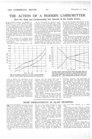
In the first graph the speed in m.p.h. is shown on the horizontal line, whilst the distance above this line indicates the amount of petrol consumed. The points so established were connected by lines, the lower solid line coveting the performance of the main jet, the dotted line of the compensating jet and the upper solid line the total of the two.
It will be noted that at 5 m.p.h. the main jet is still inoperative, the compensating jet then furnishing all the fuel which, at this speed, is automatically measured through the slow-running jet. As the speed increases, the main and compensating jets take up the work of delivery, the flow through both jets in
creasing with the speed until this is raised to between 10 and 15 m.p.h.
Somewhere between these two speeds the atmospheric well over the compensating jet as drained, and condensation then commences. Thereafter the amount of petrol flowing through the compensating jet remains practically constant; the j flow through the main et, on the other hand, shows a steady increase with the rise in speed. The figures obtained show that the actual operation of the Zenith instrument is practically identical with its theoretical performance, and that the
flow of fuel through the main jet is constantly increased as the speed of the oncoming air is increased, whilst the flow of petrol through the compensating jet is unaffected by speed increase.
Summed up, the Zenith principle of operation may be taken to be a combination of two jets, one giving a mixture of greater richness as the motor speed increases, and the other one of diminishing richness.
It is obvious that changes in the sizes of the jets only change the degree of variation, or, in other words, the extent to which each jet affects the resultant.
The second graph is made from the same data, but, in this ease the vertical divisions represent the percentage of total fuel used ; the dotted line indicates the proportion of total fuel flowing through the compensating jet, and the solid line that flowing through the main
jet. At speeds below 16 m.p.h. the greater parts of the fuel is supplied through the compensating jet. In excess of this speed the main jet supplies most of the fuel; in fact, at 40 m.p.h. the actual figure is about 78 per cent.
The graphs will certainly help those interested to understand how this form of carburetter controls the fuel entering the mixture