


Head Design for High Compression
Page 50
If you've noticed an error in this article please click here to report it so we can fix it.
ANOVEL combustion system for petrol engines forms the subject of patent No. 639.634, which comes from H. Weslake, Fullers Way, Kingston By-pass, Surbiton, Surrey. It is claimed for the scheme that much higher compression can he used without causing "pinking."
The engine has three valves per cylinder; these are an air inlet (I), a rich-mixture valve (2) and the usual exhaust (3). The combustion chamber, which contains the sparking plug, slopes down to the piston crown, in which a slight hollow is formed.
The timing is such that the air valve and the exhaust valve are, for a period, open together, so that a good scavenge is obtained. The air valve is so located that a vigorous swirl is imparted to the incoming air. The rich mixture enters the combustion space where it tends to remain, so that, at the moment of firing, the space
round the air valve contains almost only air. This cannot be detonated by the rising pressure, and it is to this feature that the anti-knock properties are ascribed.
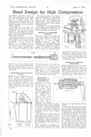
A HIGH-SPEED OIL -CHANGING PLANT
PATENT No. 639,830 conies from M. Tabet, Norfolk, Virginia, U.S.A., and deals With equipment for removing engine oil at a rate faster than the usual draining technique. Th.! outfit is intended for use at 'servicing depots which have large numbers of vehicles to deal with in as short a time as possible.
The apparatus consists of a tank on wheels, surmounted by a motor-driven pump (1). The suction side of the pump is fitted with a flexible hose terminating in a thin tubular end (2) which is small enough to pass through the dipstick hole.
By inserting the tube, and switching on the pump, it is claimed that one minute will suffice to remove the oil, which is discharged into the tank.
DIPSTICK AS IMMERSION HEATER
TO keep an engine warm under cold external conditions is the aim of a novel device shown in patent No. 639,310, by A. Peet, "Cranley." Kingsdown Avenue, Luton, Beds. Electricity is the heating medium, and no alterations to the engine are needed.
This inventor proposes to use the oil dipstick to perform the additional duty of acting as an immersion heater.
The drawing shows the tubular construction, with the heater coil (1) located in the tip. The upper end is fitted with a two-pin plug for connecting-up to an electric supply point. Mains current is envisaged, but the heater could, of course, be wound to suit the batteries of the vehicle.
IMPARTING A TOUGH SKIN TO CRANKSHAFTS
PATENT No. 639,284 comes from the Glacier Metal Co., Ltd., and W. Tait, both of
368, Ealing Road, Wembley, and makes some interesting observations on crankshaft bearings. Hitherto, with a soft crankcase, soft metals of the babbitt type have had to be used. Now, however, harder alloys such as lead-bronze are coming into favour, and these call for a somewhat harder surface on the crankshaft. To provide a fully hardened surface is, however, an expensive process, and the patent deals with a method of producing a surface which is equally satisfactory.
It is proposed to form a skin of carbon steel by the conventional carburizing process, but to leave it in the soft condition instead of quenching it out to harden it This avoids distortion and subsequent grinding, because it is the quenching-out that causes distortion.
The carburizing is performed by electric induction heating which raises the skin of the bearing to a high temperature in the presence of a carburizing agent in paste or gaseous form. A thin skin of steel containing 1 per cent. of carbon is thus produced, and is said to wear well in conjunction with a lead-bronze bearing.
HYDRAULIC STEERING MECHANISM
PIPE-LINES instead of rodwork form 1 the connecting means used in a steering system shown in patent No. 638,825, by E. Aron and A. Banning, 159a, Church Road, Hove, Sussex. In this scheme, the steering wheel works a reversible pump which operates the
• stub-axles via a double-acting hydraulic cylinder.
The drawing shows the pump unit; this works on the swash-plate principle and is mounted in the place of the usual steering column. The wobbler (1) can be turned by the steering-wheel (2) and oscillates four pistons (3). The pistons are so timed that at least two are operative at any moment. The push-pull liquid circuit is led via connections (4) to the pipework of the hydraulic cylinder. A feature of the scheme is that the reduction ratio can be varied by turning a knob (5) which adjusts the working angle of the wobbler. Presumably an external power pump would be used for heavy-vehicie arrangements.