


Cleaning Producer Gas Electrostatically
Page 36
If you've noticed an error in this article please click here to report it so we can fix it.
A Resume of Patent Specifications That Have Recently Been Published
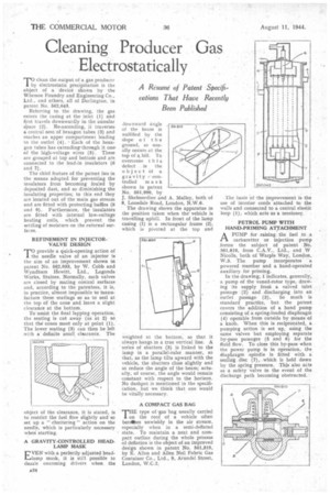
clean the output of a gas producer by electrostatic precipitation is the object of a device shown by the Whessoe Foundry and Engineering Co., Ltd., and others, all of Darlington. in patent No. 562,043.
Referring to the drawing, the gas enters the casing at the inlet (1) and first travels downwardly in the annular space (2). Re-ascending, it traverses a central nest of hexagon tubes (3) and reaches an upper compartment leading to the outlet (4). • Each of the hexagon tubes has extending, through it one of the high-voltage wires (5). These are grouped at top and bottom and are connected to the lead-in insulators (6. and 7).
The chief feature of the patent lies in the means adopted for preventing the insulators from becoming fouled by deposited dust, and so diminishing the insulating properties; to this end they are located out of the main gas stream and are fitted with protecting baffles (8 and 9). Furthermore, the insulators are fitted with internal low-voltage heating coils, which prevent the settling of moisture on the external surfaces.
REFINEMENT IN INJECTOR. VALVEDESIGN
rrio provide a quick-opening action of 1 the needle valve of an injector is the aim of an improvement shown in patent No. 56.2,033, by W. Cobb and Wyndham Hewitt, Ltd., Lagonda Works, Staines. Normally, such valves are closed by mating conical surfaces and, according to the patentees, it is, in practice, almost impossible to manufacture these seatings so as to seal at the top of the cone and leave a slight clearance at the bottom.
To assist the final lapping operation, the seating is cut away (as at 2) so that the cones meet only at point (1). The lower seating (3) can then be left with a definite small clearance. The object of the clearance, it is stated is to restrict the fuel flow slightly and so set up a " chattering " action on the needle, which is particularly necessary when starting.
A GRAVITY-CONTROLLED HEADLAMP MASK
EVEN with a perfectly adjusted head1---olamp mask, it is still possible to dazzle oncoming drivers when the downward angle of the beam is nullified by the slope of the ground, as usually occurs at the top of a hill. To overcome this
defect . is the object of a gravity controlled mask shown in patent No. 561,990, by J, Shehnerdine and A. Mulley, both of 8, Lonsdale Road, London, N.W.6.
The drawing shows the apparatus in the position taken when the' vehicle is travelling uphill. In front of the lamp casing (I) is a rectangular frame (2), winch is pivoted at the top and weighted at the bottom, so that it always hangs in a true vertical line. A series of shutters (9) is linked to the lamp in a parallel-ruler manner, so that, as the lamp tilts upward with the vehicle, the shutters close slightly and so reduce the angle of the beam; actually, of course, the angle would remain constant with respect to the horizon. No dashpot is mentioned in the specification, but we think that one would be vitally necessary.
A COMPACT GAS ISAG PrIlE type of gas bag usually carried on the roof of a vehicle often becdbes unwieldy in the air stream, especially when in a semi-deflated state. To maintain a neat and corapaet outline during the whole process of deflation is the object of an improved design shown in patent No. 561,819, by E. Allen and Allen Neil Fabric Gas Container Co., Ltd., 9, Arundel Street, London, W.C.2. The basis of the improvement is the use of interior cords attached to the walls and connected to a central elastic loop (1), which acts as a tensioner.
PETROL PUMP WITH HAND-PRIMING ATTACHMENT
APUMP for raising the fuel to a carburetter or injection pump forms the subject of patent No. 561,810. from C.A.V., Ltd., and W Nicolls, both of Warple Way, London, W.3. The pump incorporates a powered member and a hand-operated auxiliary for priming.
In the drawing, 1 indicates, generally, a pump of the vaned-rotor type, drawing its supply horn a valved inlet passage (2) and discharging into an outlet passage. (3). So much is standard practice, but the patent covers the addition of a hand pump consisting of a spring-loaded diaphragm (4) operable front outside by means of a knob. When this is reciprocated, a pumping action is set up, using the same valves but employing separate by-pass passages (5 and 6) for the fluid flow. To close this by-pass when the power pump is in operation, the diaphragm spindle is fitted with a sealink disc (7), which is held down by the spring pressure. This also acts as a safety valve in the event of the discharge path becoming obstructed.