


A Combined Disc and Shoe Brake
Page 80
If you've noticed an error in this article please click here to report it so we can fix it.
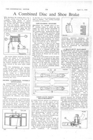
T°distribute the braking heat over a larger surface area is the aim of a composite brake shown in patent No. 790,675 which describes a combination of disc and shoe. In this scheme, the shoes are directly applied by the driver and their limited rotary movement is used as a servo to apply, the disc mechanism. (Bendix Aviation Corp., South Bend, Indiana, U.S.A.) The section shown illustrates the shoe surface (1) which is of conventional form. The disc portion comprises part of the drum (2) and an attached ring (3), the friction members (4) being arcuate strips instead of the more usual round pads.
The two mechanisms are interconnected by balls (5) housed in pockets_ having sloping ramps. When the shoe member is in action, it moves the balls up the ramps in a circumferential direction and this causes them to thrust the friction elements outward against the enclosing disc faces.
HIGHER COMPRESSION WITHOUT DETONATION
A COMBUSTION head claimed to PA enable a high compression ratio to be used without creating detonating conditions is shown in patent No. 791,115, The principle of the scheme is to divide the combustion space into separate compartments by providing upstanding ribs on the piston crown. (Jan van Tilburg, Nassauplcin 29, Alkmaar, The Netherlands.)
The drawing shows an overhead-valve cylinder, the piston of which is provided with two of these ribs (1) which extend right across the piston. To prevent the ribs themselves from reaching a high temperature, and creating detonating conditions, they are made hollow and cooled by the flow of a low melting-point metal such as sodium. The cooling passages are shown in section at 2.
LOW-LOADING TRAILERS
PATENT No. 790,888 refers to lowloading trailers in which the rear bogies are made quickly detachable to permit the load -to be moved on or off a sloping ramp. Replacing the bogies is often a troublesome operation owing to the difficulty of obtaining a precise line-up before the pins can be inserted. The scheme shown in the patent is aimed at ,facilitating this operation.. (J. Dyson. R. A. Dyson and Co., Ltd., 78-80 Grafton Street, Liverpool 8, and T. Pollard.)
The drawing is a plan of two bogie
assemblies. They are attached to the frame, by rocking pins carried in the housing (1). To remove the bogie, a locking lever (2) is released and the pins screwed out by turning a handwheel (3). This wheel turns a central drawbar which after leaving its thread can be used to pull out the pin.
The basis of the patent is that the outer sleeve of the pin is tapered so that when re-assembling, considerable misalignment can be tolerated initially because the small end of the faper has a large hole to enter. As the pin is pulled home by its screw, the parts are gradually pulled into the correct position.
LIGHT-ALLOY PISTON REINFORCEMENT
LIGHT-ALLOY pistons are inclined to -1—d suffer wear in the region of the rings and many are provided with some form of ferrous insert at this point. In . many cases, however, the difficulty of bonding the two metals and the difference in their expansion rates lead to loosening of the insert. A scheme intended to cover these disadvantages is shown in patent No. 791,175. (W. Cheney and M. Whitfield, 2 Harvard Street, Garden City, Long Island, New York, U.S.A.)
In this design the insert is made of steel wire, initially cast-in and later partly machined away to form the ring grooves. The wire may be bent to any suitable outline, but a coil-spring formation, as shown in the drawing, is typical.
The wire is shown in plan at 1 in the cast-in • condition. A subsequent machining operation produces the groove which also cuts through the steel wire, as shown in cross-section (2). _ This leaves the coils as independent c-shaped pieces which are so small andseparate as to be unaffected by differential expansion rates.
A HEAVY-DUTY BALL-JOINT
LLIGHT-DUTY ball joints such as used in steering linkages will, if initially lubricated, work for a long time without further attention. But ball-joints used for the pivots of independent suspension sys-. terns require more frequent lubrication. Patent No. 791,069 shows a joint of this type that is claimed to be "greased-forlife." (Thompson Products Inc., 23555 Euclid Avenue, Cleveland, Ohio, U.S.A.) In the section illustrated, the joint is shown uniting the two members of an independent . suspension, system. One part cornprises a ball-headed holt (1) which carries on its shank a hardened steel part-spherical bush (2). Both these components are enclosed by steel pressings which are permanently joined by -turnover lips, one of which is shown at 3. The basis of the patent is that except where the bolt-head touches the cap, there is, no metal-to-metal con
tact whatever. This is achieved by interposing thin layers of plastics material between the working surfaces; • these are indicated by the alternate heavy and light cross-hatching in the drawing.
Suitable plastics are those of the polyamide type, or polyethylene. These are tough enough to be durable, but have a limited cold flow which enables the parts to make an intimate fit in spite of unmachined surfaces.