


FORDSON TRACTOR AS A "COMPONENT."
Page 32
If you've noticed an error in this article please click here to report it so we can fix it.
A Resutine of Recently Published Patents.
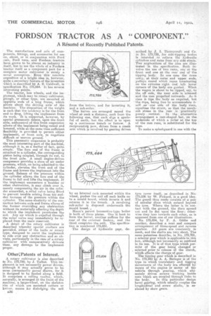
The manufacture aud sale of components, fittings, and accessories for use on, about, or in conjunction with Ford ears, Ford vans, and Fordson tractors have grown to be almost an industry in itself, but to use the whole of a Forasos tractor itself as a component part for a e,omplete motor cultivator is surely a novel conception. Even this concrete exposition of a bright idea is, however, quite a secondary feature of the invehtion which is described by A. S.•Caldwell, in Specification Ns. 175,664. It has Several
interesting points. . •
The tsactor, less wheels, and the implement, which may be raary cultivator; plough, or other type, are mounted at opposite ends of a long frame, which pivots about the driving axleof the machine. The disposition of the weight is such that the tendency is for the front end to drop, lifting the implement from its work. It is supported, however, by special pneumatic means, upon the front axle, andicontrol of this front suspension allows of the implement being raised and lowered, while at the same time sufficient flexibility is provided to permit either implement, or front axle, to negotiate difficult or uneven ground.
This pneumatic suspension is probably the most interesting part of the machine, although it is, as a matter of fact, quite simple. The fore end of the frame is attached to a cylinder' the corresponding piston being coupled, through its rod, to the front axle. A small engine-driven compressor provides a store of air under pressure, which, on being admitted to the cylinder, elevates the front end of the frame and lowers the implement into the ground. Release of the pressure within ...he cylinder allows the fore end of the frame to fall and lifts the implement. If the implensept encounters a boulder or other obstruction, it may climb over it, merely compressing the air in the cylinder somewhat, a relief valve being ,ffited to prevent trouble arising from too sudden increase of the pressure within the cylinder. The same elasticity of the connection between axle and frame allows of the former overriding any obstruction. without its materially affecting the depth to which the implement penetrates the soil. Airy air which is expelled through the relief valve may immediately be replaced from the main reservoir.
A detail of the rotary cultivator is described whereby special coulters are provided, either of the knife or rotary type, designed to assist the implement to ride over any obstruction and so obviate, particularly in the case of a rotary cultivator with comparatively delicate tines, any damage to the implement proper.
Other; Patents of Interest.
A rotary cultivator is also described En No. 175,750, by J. Talbot. This implement is not necessarily power driven, although it may actually prove to be more conveniently power drawn, for it is designed to be hauled along a field. It comprises a rolling coulter, which, naturally, is arranged at the front of the machine, a large#wheel, on the skeleton rim of which are mounted cutters or knives, means fc.r dislodging—the soil a36 from the knives, and for inverting it, and a sub-soiler.
The knives are arranged round the wheel at such a distance, each from the following one, that each -digs a spadeful of earth, but the effect is to open up a continuous trench or furrow. A reciprocatieg paw, driven from a crank arm which is revolved by gearing driven
by an internal rack mounted within the wheel, pushes the soil off each knife on to a mould board, which inverts it and returns it to the trench. A revolving sub-soiler is disposed underneath the mould beard. , Mann's patent locomotive-type boiler is built of three plates. One is bent to form the barrel, another, suffices for the rear of the external firebox and the third completes the unit. The specification is numbered 175,851.
-The design of hydraulic getr, de scribed by J. I. Thornycroft and Co. in No. 175,739, for side-tipping bodies is intended to relieve the hydraulic cylinders nod rains froth any side strain. 'two applications of the idea are illustrated in the specification. Both involve the use of two rams, one at the -..front and one at the rear end of the tipping body. In one case the rains carry,. at their outer and upper ends, pulleys round which ropes terminating on the extreme right and left lower corners of the hody are guided. Wheh the wagon is about to be tipped, say, to the. off .side, the near side. is released and the ram propelled outwards. As it rises it tips the body as required, but the rope, being free to accommodate itself as one side of the body rises, equalizes the strain, so that the resultant stress in the . ram is • practically
purely .. vertical. In the. alternative arraugeMent a cam-shaped bar, on the underside of which a roller at the top of the ram runs, is substituted for the rope, To make a splashguard in one with the tyre cover itself, as described in No 175,8,36 by W. Pickard, is a good idea The guard thus made consists of sc pair of annular discs which extend beyond the tyre. Where the latter is in contact with the ground, the discs spread eut and lie flat upon the floor; otherwise they lean towards each other, as is apparent from one of our illustrations. No. 175,854, by F. A. Oddie and another, describes a neat and compact arrangement of three-speed and reverse gearbox. All gears are constantly in mesh, and the shafts are very short. The same patentees describe, in No. 175,701, a selector gear which is Applicable to this box, although not necessarily so confined in its use. It is of that type which permits of the gear being changed or selected •prior to release of the clutch, which effects the change of gear.
The tipping gear which is described in No. 175,843 by A. A. Stringer is of the type in which translatory and tipping movements of the body are effected by means of the engine or motor of the vehicle through gearing, which ultimately drives screws working inside nuts which are coupled through links to the body. In this particular design beVel gearing, which usually couples the longitudinal and screw shafts, is replaced by skew gears.