


A 170 b.h.p. V8 fru Perkins
Page 60
Page 62
Page 65
If you've noticed an error in this article please click here to report it so we can fix it.
L
. ONG awaited by the commercial vehicle industry, the release today of official
news of the Perkins V8 automotive diesel is of very special interest because
of the anticipated ascendancy of this form of unit in high-powered, high-speed trunking vehicles. According to Perkins technicians, the bore-stroke ratio of 1 to 1.06 represents the best compromise in providing the optimum combination of low-speed torque, power output, fuel consumption, power-to-weight ratio and package size. It is significant that stress tolerances give ample scope for turbocharging and the use of the unit as the basis of a differential diesel engine (DDE) power pack. The unit, known as the V8.510, is the most powerful automotive diesel that has been produced by the company and later it will be manufactured in a new plant covering 130,000 sq. ft. and costing some £3 m.
The V8.510 will be displayed for the first time at the British Exhibition in Tokyo from September 17 to October 3 and at the Stockholm Technical Fair from October 1 to 10. It will make its &but in Britain in the Scottish Motor Show, Kelvin Hall, Glasgow, open from November 12 to 20. Operators will then be given the opportunity to order vehicles equipped with the unit.
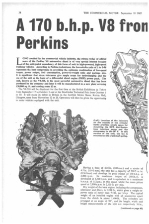
Having a bore of 4-25 in. (108 mm.) and a stroke of 4.5 in, (114.3 mm.) the unit has a capacity of 510-7 Cu. in. (8.36 litres) and develops its peak output of 170 b.h.p. at 2,800 r.p.m. Its maximum torque of 380 lb. ft. is developed at 1,500 r.p.m. and is equivalent to a maximum b.m.e.p. of 112 p.s.i. at this speed, whilst the mean piston speed at 2,800 r.p.m. is 2,100 ft. per min.
Dry weight of the bare engine, including the compressor, alternator and filters, is 1,238 lb., which gives a weight-topower ratio of better than 7-5 lb. per b.h.n. The typical weight of an installed engine with all accessories apart from the clutch is about 1,400 lb. The cylinders are arranged at an angle of 90°, and the length, width and height measurements of the unit are respectively 36 in., 33 in. and 32.5 in. A direct-injection combustion system is employed, whilst the compression ratio is 17-5 to I.
Although a comparable power output could have been obtained from a six-cylinder V engine of the same capacity, preference was given to a V8 configuration because it offered a more compact unit and freedom from critical vibration problems. The decision to build a V was taken in 1956, and whilst the first prototype was an indirect-injection unit, development was switched to direct injection in 1963 to improve fuel. consumption. No consumption figures are currently available for the V8.510, but a notably good fuel economy is claimed.
Technical interest may be centred on the use of an undersquare bore-stroke ratio in preference to an oversquare ratio and of two valves per cylinder in place of four valves. It is emphasized by Perkins designers that established conventional techniques have been applied to the design of all component parts of the engine. Their main objective has been to obtain the optimum balance of known variables in accordance with the needs of vehicle manufacturers and operators, so that the advantage of compact packaging can be exploited to the full.
Special mention is made of the merits of the longer stroke engine in terms of increased m.e.p. Technicians of the company state that this more than offsets the advantage of the oversquare unit of operating at higher r.p.m. for, a given piston speed, notably with regard to low-speed torque and overall fuel consumption.
They also point out that the high torque of the engine reduces the frequency of gear changing and enables a relatively low-cost transmission system to be employed. It is emphasized, however, that the V8.510 has a substantial " overspeeding capacity " and that this is of special importance in some overseas countries, notably in America, because of the ham-fisted tendencies of the drivers. Generous stressing tolerances permit safe overspeedine without valve bounce up to 5,000 r.p.m.
Because a longer stroke would have increased the spread of the cylinders, and therefore the frontal area of the unit unacceptably and would have necessitated a reduction in r.p.m., it was not possible to employ the bore-stroke ratio of 1 to 1.3 that has proved its worth in the case of the Perkins 6.354 engine. But the Perkins view is that the compromise ratio of 1 to 1-06 may be considered as the optimum ratio for a V8 engine. Although piston friction is somewhat greater than that of an oversquare engine developing the same power at a higher r.p.m.. the penalty is small relative to the gain in efficiency.
Contrasting the merits of the two-valve cylinder head with the four-valve type, it is claimed that the former provides better control of filling and combustion than the latter particularly if the inlet ports are accurately machined as in the case of the V8.510 which affords uniformity of filling and facilitates direction of gas flow to give planned turbulence.
According to Perkins, it is therefore possible to obtain a volumetric efficiency comparable with that offered by the four-valve head and at the same time give an efficiencypromoting swirl pattern that is created early in the stroke and is not dependent on squish. The diameter of the inlet ports is 1-437 in., whilst the exhaust-port diameter is 1-346 in. Each valve is closed by two springs.
Also of importance with regard to reducing fuel consumption (and to improving startability) the DPA distributor-type injection pump incorporates a variable-speed mechanical governor and an automatic advance-and-retard injection-timing mechanism. Hand priming is provided by the diaphragm-type fuel-lift pump.
The injectors are located centrally in the combustion chamber; they are of the conventional four-hole type and spray into pintle-centred flat-bowl combustion chamber in the piston crown. Of high-silicon aluminium alloy, the pistons have a depth of approximately 4-875 in., which affords an ample bearing surface, and are equipped with three compression rings and two oil-control rings: one of the oil rings is fitted below the fully floating gudgeon pin, which has a diameter of 1-625 in.
When considering features of the cylinder block/crankcaselcrankshaft assembly, it is noteworthy that ample bearing areas are combined with a structure the rigidity of which is enhanced by the use of dry liners and extension of the crankcase sides below the crankshaft to form a stiffening skirt.
Finished internally to provide a good oil-retaining surface, the dry liners simplify maintenance as well as improving stiffness and obviating distortion of the bores. Pre-finished slip-fit liners will later be available as service replacements. The big ends of the connecting rods of opposite cylinders are located side by side on the same crankpin, and offsetting the cylinder banks to accommodate this layout offers the advantage of increased space for the journals.
Each of the 'five induction-hardened main-bearing journals has a diameter of 4 in. and the total effective projected area of the bearing is 22-62 sq. in. The diameter and projected area of the crankpins—which are also induction-hardenedare respectively 3.25 in, and 7.93 sq. in. The crankshaft is of chrome-molybdenum steel
id has hollow crankpins spaced at 90, which enables LII balancing to be obtained by the attachment of weights
■ webs Nos. 1, 2 and 3 and 6, 7 and 8. A torsionalbration damper is bolted to a drive pulley spline-mounted the front of the shaft.
Particular attention has been given to the design of the innecting rods, which are high-tensile steel stampings ith H-section shanks and have big-end facings inclined 37.5° to the rod axis to provide for withdrawal of the stons through the top of the cylinders. Both the big-end id main bearings are of the thin-wall prefinished type, hilst the small ends are steel-backed wrapped bushes with lining of lead bronze.
In common with the cylinder block, the two cylinder :ads are of high-duty cast iron and are secured to the ock by studs and setscrews. The camshaft, of the same aterial, is located between the cylinder banks and ipported by five bearings of 2-25 in. diameter. The chilled .st-iron, spherical-faced, mushroom-type tappets are ipported in pairs in cast-iron blocks mounted in the V id the valves are operated by solid push rods, thence by el rocker levers fitted with lead-bronze, steel-backed rapped bushes. Tappet adjustment is provided by a rew and lock nut at the push-rod end of the rocker lever. Rockers and valve gear are lubricated by an intermittent ed of oil from a camshaft bearing to the four hollow icker shafts. Two rocker shafts are fitted to each head id each section of the valve gear has a separate cover. Of special importance with regard to the facility the unit fers for mounting ancillaries in the V, the injectors are cated on the outside of the cylinder banks. This also nplifies maintenance. It has the marginal disadvantage at it increases the length of the injection pipes.
Helical gears are used to transmit the drive to the camiaft from the front of the crankshaft, and a small miliary crankshaft mounted above the camshaft and iven by this shaft at engine speed is used to operate the impressor and lift pump, the fuel-injection pump being ounted at the front of the V and driven by the auxiliary tar. The top half of the two-piece timing case is of uminium, whilst the lower half is of cast iron.
Attached to the underside of the crankcase, the gearpe oil pump of the lubrication system is driven from the ankshaft gear via an idler, a plunger relief valve being ied to control the maximum oil pressure. Oil is drawn trough a perforated sheet type of strainer and on the :livery side passes through a twin-bowl, full-flow filter on s way to the main gallery of the cylinder block. Provision made for connecting the filter head to an oil cooler and tapping in the head can be employed for the fitment of pressure-warning switch or gauge.
Oil is carried from the gallery to the main bearings trough drilled holes in the main-bearing housing webs and fed to the big-end bearings from the mains through drilled holes in the crankshaft. Cylinder bores, small ends and gudgeon pins are splash lubricated.
A cast-aluminium sump of the well type, with a capacity of 23 pints, is a standard fitting and is reversible to allow the well to be located at either end with appropriate positioning of the oil pump. Alternative sump arrangements are available to cater for individual requirements.
Features of the cooling system include a centrifugal-type water pump, which is mounted high on the timing case and is belt driven from the crankshaft pulley. This pulley k available in modified form with a special adapter for direct attachment of a pressed-steel fan, if this is preferred to mounting the fan on the water-pump pulley.
Coolant is delivered simultaneously to a cast-in gallery in each cylinder bank and is directed to the cylinder head through drilled and cored holes, the dimensions and shapes of the passages being carefully controlled to promote uniform heat gradients. A thermostat is located at each of the outlets at the front of the cylinder heads.
Positioned on the inner side of the banks, the two induction manifolds are of aluminium alloy, whilst the exhaust manifolds arc of cast iron and are also bolted to the heads. The outlet connection flanges of the standard automotive exhaust manifold are arranged to face downwards and are positioned centrally, but alternative arrangements are available. Alternative types of induction manifold can also be supplied.
Current is supplied by a 12V or 24V belt-driven alternator, according to the system employed, belt tension being adjustable by means of a slotted link. Two standard sizes of air-brake compressor are available mounted on a platform in the V and driven at engine speed from the camshaft. One has an output of approximately 9 Cu. ft. per min. free-air delivery at 1,200 r.p.m. and a smaller unit is rated at 6 cu. ft. per min. at this speed. A refrigeration compressor can also be supplied, which is driven in tandem with the brake-system compressor.
Other optional accessories include a steering-servo hydraulic pump, which is designed 'for mounting on the left side of the timing case at the front and which is driven from the timing-gear train. Cold-starting options comprise a Thermostart system, which caters for starting down to —5°F (-20°C), and an ether-start device which provides for starting down to —20°F (-29°C),.