


TWO NEW PASSENGER CHASSIS
Page 58
Page 59
Page 60
If you've noticed an error in this article please click here to report it so we can fix it.
from an Old-established British Works
First Descriptions of Two Dennis Low-loading Models Designed to Carry Coach or Bus Bodies Accommodating 32 Passengers : For ward or Normal-control Positions Provided.
A MONG the extensive range of passenger and goodsLicarrying vehicles marketed by Dennis Bros., Ltd., Guildford, are two new types XDOIVII1 as the EV and FS, having 'forward or normal control positions, respectively. • These are designedexpressly to meet
modern passenger-travel needs. In addition, great care has been taken to provide easy maintenance.
The. two types may be dealt with as one, the principal points of difference being in the control position, ; as already mentioned, and in the design of the radiator. The ..FS. type has a. cast-aluminium radiator of the familiar. Dennis pattern, whilst the EV or forwardcontrol machine has a radiator of novel construction. Throughout this description we refer to the-E.V. primarily, but, in general, the remarks apply to both types. . Brackets •a r e bolted to the front ends of the main frame members, and these carry, upon rubber cushions, the castaluminium base tank of the,ra:dia7 tor, upon . which are mounted in turn the tub e block, side-pieces and east-aluminium header tank. The whole is covered by a detachable nickel shell with a grid to mask the tubes of the radiator proper. At the front the main-frame members have a depth of Bf ins., reaching a maximum of 7 ins, and tapering to 5 ins, at the extreme rear ; the horizontal webs are 2/ ins, wide, a-in. steel being used. In elevation these members are cranked downwards at the dash line .and then run horizontal to the rear except for a small,. upsweep over the rear axle. In plan the
frame members are parallel throughout, and seven cross-members are employed.
Four brackets are fixed to the frame to support the gearbox. This is carried upon two girders which have their extremities bolted up to the brackets on the frame. After removing the four bolts the gearbox can be dropped, the nniversal joints and speedometer drive having been previously disconnected.
, Semi-elliptic springs are used for both axles. They are pivoted at the front and shackled at the rear. In the former ease 12 leaves 2/ ins, wide are employed, the top ones being rebound leaves, the main ones having solid eyes. The rear springs are 3 ins, wide and have 11 leaves, but none of the rebound pattern. They are retained by +in, bolts which are a press fit into the saddles of the axle casing.
Simple Layout of Brake Controls.
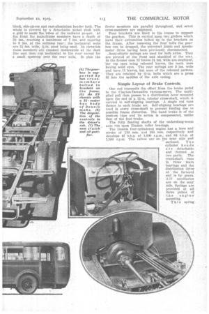
One rod transmits the effort from the brake pedal to the Clayton-Dewandre vacuum-servo. The multiplied pull then passes to a distribution lever mounted upon the end of a 11-in, tubular cross-shaft, which is carried in self-aligning bearings. A single rod runs thence to each brake set. Self-aligning bearings are used in every cross-shaft to prevent binding due to possible frame distortion. The hand brake is of the push-on type and its action is compensated, unlike that of the foot 'brake. • The fully floating shafts of the underslung-worm axle run upon Timken roller hearings.
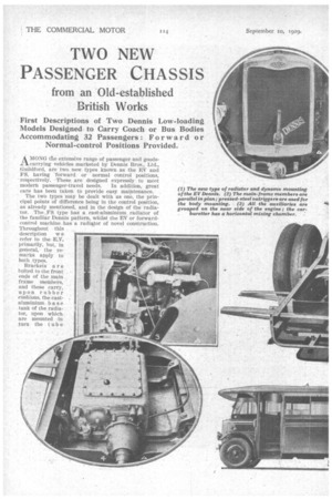
The Dennis four-cylindered engine has a bore and stroke of 110 mm. and 150 mm. respectively and develops 47 b.h.p. at 1,000 r.p.in., and 64 b.h.p. at 1,500 r.p.m. The valves are on • the near side and — enclosed. T h e cylinder h e a dts are . detachable and formed in two parts. The crankshaft runs in three main bearings and the distribution drive' at the forward end is by gears. A ii auxiliaries are on the near side. Springs are provided at all three points of the , engine mounting.
This spring
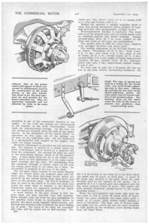
mounting is one of the noteworthy features of the engine. At the front the springs are incorporated in the bracket, on the front cross-member, which holds the ball-and-socket bearing. At the rear the coil springs are mounted above the ends of the engine bearer. In the ,illustration of the clutch, which we reproduce on this page, one of the springs can be seen on the right-hand side. On the dashboard is a spring-loaded link coupled to the engine; this takes the torque reaction.
Eccentric Adjustment is provided for the belt-driven fan. The dynamo is carried in a saddle below the front cross-member and is driven by a separate belt from the crankshaft. No external oil pipes are used in the main-supply system, Which is of the pressure type. A gear pump feeds the oil to the hollow camshaft which in turn distributes it to the main crank, shaft bearings and big ends. Oil overflowing from the camshaft—through a release valve—is led past the timing gears back to the sunup via a filter. An oil purifier is mounted on the rear of the dash.
The dry-plate clutch consists of two fabric floating rings, one driven plate, one pressure plate and one outer plate. The three bell-crank levers, which are operated by the central spring, bear upon three cam faces on the pressure plate. All that is necessary to take up wear in the clutch is to undo two studs and rotate the cover plate in relation to the flywheel. Fabric-disc joints are employed between the clutch and the separately mounted gearbox.
A novel feature of the gear, change is that the lever shaft can slide laterally upon ball bearings. Three selector rods run from the gate mechanism to the gearbox, there being an interlocking device to prevent two gears being engaged simultaneously, and internal and external locks to prevent the gears sliding out of mesh. The faces of the teeth are exception, ally wide, and the shafts run on ball bearings. The
ii34
ratios are: Top, direct; third, 1.7 to 1; second, 2.97 to 1; first and reverse, 5.06 to 1.
Behind the gearbox a tubular propeller shaft D.' used, this having mechanical joints enclosed in lams jugs provided with spring-loaded, oil-tight covers.
Worm-and-sector steering is employed. The front axle is of the dropped type, and the swivel heads work on combined journal and thrust bearings. Dunlop straight-sided, 38-in. by 7 in. tyres (singles at the front and twins at the rear) are standardized.
The chassis price is £885 for either type, complete with outrigger brackets and seven tyres.
The leading dimensions of the By-type Dennis are as follow: Wheelbase, 16 ft. 6 ins.; front track, 5 ft. 11 ins.; rear track, 5 ft. 6 ins.; dash to end of frame, 21 ft. 1 in.; overall length, 25 ft. 4 ins.; overall width, 7 ft. 2 ins; height of frame from ground (loaded), 26 ins.; turning circle, 59 ft.; clearance under rear axle, 7 ins.; approximate chassis weight, 3 tons 5 cwt.
We were able to take out a 32-seater EV bus for test in the hilly district surrounding Guildford. On
the 1 in 10 portion of the climb up to the Hog's Back the speed was 20 m.p.h. in third gear. A speed of 36 m.p.h.. was reached at the point where the road becomes level at the summit of the ascent. Up a gradient of 1. in 7, second gear was employed and the bus never dropped below 14 m.p.h. The engine ran with unusual sweetness, thanks partly to. the spring mounting points.•
When the servo-assisted foot, brake wb.s used the bus came to rest in about 39 yards front 40 null. Under the same conditions the hand brake gaVe a result of 47 yards. Both brakes • acted without .a trace of ,harshness. 'The body, also of Dennis -make, was silent and the vehicle -did not roll when cornering at high speeds on the secondary roads leading ',down from the Hog's–Back.